Table of Contents
Advertisement
Advertisement
Table of Contents

Related Manuals for Exmark SAR481KA30


Summary of Contents for Exmark SAR481KA30
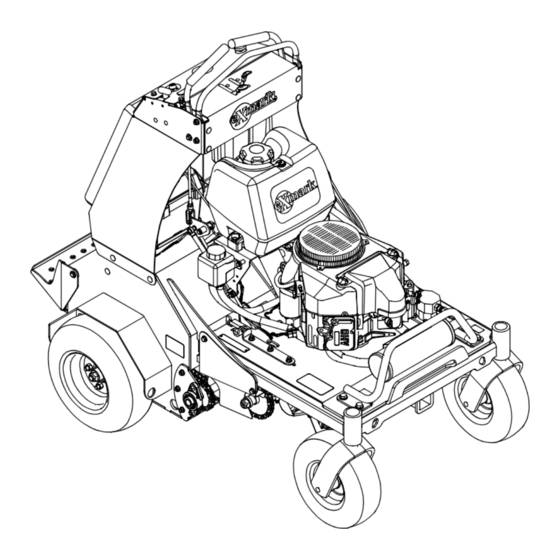
- Page 1 STAND-ON AERATOR For Serial Nos. 312,000,000 & Higher Part No. 4501-251 Rev. A...
- Page 2 Replacements may be ordered through the engine manufacturer. Exmark reserves the right to make changes or add improvements to its products at any time without incurring any obligation to make such changes to products manufactured previously.
-
Page 3: Introduction
All Exmark parts are thoroughly tested and inspected before leaving the factory, however, attention is required on your part if you are to obtain the fullest measure of satisfaction and performance. -
Page 4: Table Of Contents
Contents Transmission Drive Belt Tension Adjustment ..........30 Jackshaft Drive Chain Tension Introduction ............3 Adjustment ..........30 Safety ..............5 Drive Wheel Chain Tension Safety Alert Symbol ......... 5 Adjustment ..........31 Safe Operating Practices ........5 Tine Drive Chain Adjustment ......31 Safety and Instructional Decals ......10 Adjusting the Parking Brake......31 Specifications ............13... -
Page 5: Safety
WARNING, or CAUTION. safely perform the job. Only use accessories and DANGER: White lettering / Red background. attachments approved by Exmark. Indicates an imminently hazardous situation which, if • Wear appropriate clothing including safety glasses, not avoided, Will result in death or serious injury. - Page 6 Safety DANGER DANGER In certain conditions gasoline is extremely In certain conditions during fueling, static flammable and vapors are explosive. electricity can be released causing a spark which can ignite gasoline vapors. A fire or A fire or explosion from gasoline can burn explosion from gasoline can burn you and you, others, and cause property damage.
- Page 7 Safety Operation WARNING Hands, feet, hair, clothing, or accessories can WARNING become entangled in rotating parts. Contact Operating engine parts, especially the muffler, with the rotating parts can cause traumatic become extremely hot. Severe burns can occur amputation or severe lacerations. on contact and debris, such as leaves, grass, •...
- Page 8 Safety • Reduce tine down pressure to prevent the drive • Carefully release pressure from components with tires from raising off the ground and to prevent stored energy. the front tires from raising off of the ground • Disconnect battery or remove spark plug wire while aerating uphill.
- Page 9 – Safely relieve all pressure in the ground and safety of the machine. Failure to use original drive hydraulic system by placing the motion Exmark parts could cause serious injury or control levers in neutral and shutting off the death. Making unauthorized changes to the engine.
-
Page 10: Safety And Instructional Decals
Exmark equipment dealer or labels. distributor or from Exmark Mfg. Co. Inc. • Replace all worn, damaged, or missing safety • Safety signs may be affixed by peeling off the signs. - Page 11 Safety 116-6459 116-7709 116-6460 116-6462 116-6990...
- Page 12 Safety 116-7027 1. Fast 5. Wheels and tines rotate when moving forward 6. Wheels and tines rotate when moving rearward 2. Slow 3. Neutral 7. Choke–on 4. Reverse 8. Choke–off 116-7611 1. Rotate counterclockwise to decrease pressure 3. Park brake—release 2.
-
Page 13: Specifications
• Engine Specifications: See your Engine Owner’s Safety Interlock System Manual Engine will not start unless the park brake is engaged. • Engine Oil Type: Exmark 4–Cycle Premium Engine Oil Operator Controls • RPM: Full Speed: 3600 ±100 RPM (No Load) •... -
Page 14: Dimensions
Specifications Tires and Wheels Torque Requirements Drive Front Caster Bolt Location Torque Engine Mounting Bolts 17-23 ft-lb (23-31 N-m) Pneumatic Semi-Pneumatic (Air-Filled) Wheel Lug Nuts 90-95 ft-lb (122-129 N-m) Quantity Wheel Hub Nuts 140-155 ft-lb (190-210 N-m) Tread Super Turf Smooth Size 16 x 6.50-8... -
Page 15: Product Overview
Operation Product Overview Operation Note: Determine the left and right sides of the machine from the normal operating position. Controls Motion Control Levers The motion control levers, located on each side of the top console, control the forward and reverse motion of the machine. - Page 16 Operation engaged. The unit must be tied down and brake engaged when transporting. Ignition Switch Located on the right side of the control console (see Figure 5). The ignition switch is used to start and stop the engine. The switch has three positions “OFF”, “ON” and “START”.
-
Page 17: Pre-Start
Operation Tines Ground Engagement Foot Starting the Engine Switch 1. Leave the motion control levers in neutral and engage the parking brake. Keep hands and feet away from the tines. Make sure the tines area is clear of any obstructions 2. - Page 18 Operation Raising the Tines To raise the tines, remove your foot from the tine ground engagement foot switch. Important: The tines are rotating when the motion control lever is moved out of the neutral position. Stopping the Engine Figure 7 1.
-
Page 19: Transporting
Operation Important: Do Not make a zero turn when has all necessary lighting and marking as required by the tines are down as turf tearing will result. law. Secure a trailer with a safety chain. The machine will move faster the farther the CAUTION motion control levers are moved from the neutral position. - Page 20 Operation loading on or near a slope, position the trailer or truck so it is on the down side of the slope and the ramp extends up the slope. This will minimize the ramp angle. The trailer or truck should be as level as possible.
-
Page 21: Maintenance
Maintenance Maintenance Note: Determine the left and right sides of the machine from the normal operating position. WARNING WARNING While maintenance or adjustments are being The engine can become very hot. Touching a hot made, someone could start the engine. engine can cause severe burns. -
Page 22: Periodic Maintenance
“FULL” of 12.6 volts or greater. mark on the dipstick. Exmark 4-Cycle Premium Important: Make sure the negative battery cable Engine Oil is recommended; refer to the Engine is disconnected and the battery charger used for Owner's manual for an acceptable alternative. - Page 23 Maintenance Note: The following instructions are adapted Voltage Percent Maximum Charging from the SAE J1494 Rev. Dec. 2001 – Battery Reading Charge Charger Interval Booster Cables – Surface Vehicle Recommended Settings Practice (SAE – Society of Automotive 11.7–12.0 0–25% 3 Hours 14.4 volts/4 Engineers).
-
Page 24: Check Tines
1. Stop engine, wait for all moving parts to stop, and Note: If the machine does not pass this test, do not remove key. Engage parking brake. operate. Contact your authorized Exmark Service 2. Lift the rear of the unit and support using jack Dealer. -
Page 25: Change Engine Oil
See Auxiliary Pump remove cap. Oil level should be to the top of the Drive Belt Adjustment in the Adjustments baffle inside the tank. If not, add oil. Use Exmark section. Premium Hydro Oil. Replace hydraulic reservoir 4. -
Page 26: Check Condition Of Chains
Maintenance Check Condition Of Chains WARNING Engine must be running and drive wheels Service Interval: Every 50 hours must be turning so adjustments can be 1. Stop engine, wait for all moving parts to stop, and performed. Contact with moving parts or hot remove key. -
Page 27: Lubricate Caster Wheel Hubs
6. Pack the bearings with a NGLI grade #1 multi-purpose grease. 7. Insert one bearing, one new seal into the wheel. Note: Seals (Exmark P/N 103-0063) must be replaced. 8. If the axle assembly has had both spacer nuts removed (or broken loose), apply a thread locking adhesive to one spacer nut and thread onto the axle with the wrench flats facing outward. -
Page 28: Change Auxiliary Hydraulic Reservoir Fluid And Filter
1. Stop engine, wait for all moving parts to stop, and Important: Before reinstalling new filters, remove key or spark plug wire(s). Engage parking apply a thin coat of Exmark Premium Hydro brake. Oil on the surface of the filters rubber seal. -
Page 29: Wheel Hub Nut And Transmission Output Shaft Torque Specification
Maintenance Torque the nut on the wheel motor tapered shaft to CAUTION 140-155 ft-lb (190-210 N-m). Raising the unit for service or maintenance Note: Do Not use anti-seize compound on the relying solely on mechanical or hydraulic wheel hub. jacks could be dangerous. The mechanical or hydraulic jacks may not be enough support or may malfunction allowing the unit to fall, Check Spark Arrester... -
Page 30: Adjustments
Maintenance Adjustments Note: Shut off engine, wait for all moving parts to stop, engage parking brake, and remove key before servicing, cleaning, or making any adjustments to the unit. CAUTION Raising the unit for service or maintenance relying solely on mechanical or hydraulic jacks could be dangerous. -
Page 31: Drive Wheel Chain Tension Adjustment
Maintenance 5. Tighten hydro mounting bolts. 6. Engage the park brake. 6. Adjust motion controls as stated in the Motion 7. Adjust the nut position until 3 1/8 inch (7.9 cm) Control Linkage Adjustment section. from the bottom of link to bottom of spring. See Figure 13. -
Page 32: Motion Control Linkage Adjustment
Maintenance Figure 15 1. Clevis pin 3. Cotter pin 2. Turnbuckle 5. Holding the control levers forward, rotate the Figure 14 turnbuckle clockwise until there is a minimal gap 1. Park brake switch 2. 1/8 inch (3.2 mm) gap or contact between the control lever and the front bracket reference bar. -
Page 33: Cleaning
Maintenance Cleaning Clean Engine and Exhaust System Area Service Interval: Before each use or daily (May be required more often in dry or dirty conditions.) CAUTION Excessive debris around engine cooling air intake and exhaust system area can cause engine, exhaust area, and hydraulic system to overheat which can create a fire hazard. -
Page 34: Waste Disposal
Maintenance guards, around the fuel tank, around engine and exhaust area. Waste Disposal Motor Oil Disposal Engine oil and hydraulic oil are both pollutants to the environment. Dispose of used oil at a certified recycling center or according to your state and local regulations. -
Page 35: Troubleshooting
Troubleshooting Troubleshooting Important: It is essential that all operator safety mechanisms be connected and in proper operating condition prior to use. When a problem occurs, do not overlook the simple causes. For example: starting problems could be caused by an empty fuel tank. The following table lists some of the common causes of trouble. - Page 36 Troubleshooting Problem Possible Cause Corrective Action Engine overheats. 1. Engine load is excessive. 1. Reduce the ground speed or aeration depth. 2. Oil level in the crankcase is low. 2. Add oil to the crankcase. 3. Cooling fins and air passages for the 3.
-
Page 37: Schematics
Schematics Schematics Electrical Diagram... - Page 38 Schematics Electrical Schematic...
- Page 39 Schematics Hydraulic Diagram...
- Page 40 No Claim of breach of warranty shall be cause for cancellation provided by Exmark. or rescission of the contract of sale of any Exmark mower. There are no other express warranties except for engine and All implied warranties of merchantability (that the special emission system coverage.
- Page 41 Service Record Date: Description of Work Done: Service Done By:...
- Page 43 G011841 Figure 17 This page may be copied for personal use. 1. The maximum slope you can safely operate the machine on is 15 degrees. Use the slope indicator to determine the degree of slope of hills before operating. Do Not operate this machine on a slope greater than 15 degrees. Fold along the appropriate line to match the recommended slope.
- Page 44 Pack) or Fill in Below Engine Model No. and Spec. No. Model No. Engine Serial No. (E/No) Serial No. ©2012 Exmark Mfg. Co., Inc. Part No. 4501-251 Rev. A 2101 Ashland Ave (402) 223-6300 Beatrice, NE 68310 Fax (402) 223-5489...