
Related Manuals for Exmark ARS180KA21


Summary of Contents for Exmark ARS180KA21
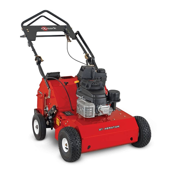
- Page 1 21 INCH WALK-BEHIND AERATOR For Serial Nos. 314,000,000 & Higher Part No. 4501-882 Rev. A...
- Page 2 Replacements may be ordered through the engine manufacturer. Exmark reserves the right to make changes or add improvements to its products at any time without incurring any obligation to make such changes to products manufactured previously.
-
Page 3: Introduction
All Exmark parts are thoroughly tested and inspected before leaving the factory, however, attention is required on your part if you are to obtain the fullest measure of satisfaction and performance. -
Page 4: Table Of Contents
Contents Adjusting the Tine Ground Engagement Lever............27 Cleaning ............28 Introduction ............3 Clean Engine and Exhaust System Safety ..............5 Area ............28 Safety Alert Symbol ......... 5 Clean Debris From Machine ......28 Safe Operating Practices ........5 Waste Disposal ..........28 Safety and Instructional Decals ....... -
Page 5: Safety
Indicates an imminently hazardous situation which, if safely perform the job. Only use accessories and not avoided, Will result in death or serious injury. attachments approved by Exmark. WARNING: Black lettering / Orange background. • Wear appropriate clothing including safety glasses, Indicates a potentially hazardous situation which, if substantial footwear, and hearing protection. - Page 6 Safety DANGER DANGER In certain conditions gasoline is extremely In certain conditions during fueling, static flammable and vapors are explosive. electricity can be released causing a spark which can ignite gasoline vapors. A fire or A fire or explosion from gasoline can burn explosion from gasoline can burn you and you, others, and cause property damage.
- Page 7 Safety Operation • Stop engine, wait for all moving parts to stop: – Before refueling. WARNING Operating engine parts, especially the muffler, WARNING become extremely hot. Severe burns can occur Hands, feet, hair, clothing, or accessories can on contact and debris, such as leaves, grass, become entangled in rotating parts.
- Page 8 Unauthorized modifications to the original • Always avoid sudden starting or stopping on a equipment or failure to use original Exmark slope. parts could lead to serious injury or death. • Follow the manufacturer’s recommendations for...
-
Page 9: Safety And Instructional Decals
Exmark equipment dealer or labels. distributor or from Exmark Mfg. Co. Inc. • Replace all worn, damaged, or missing safety • Safety signs may be affixed by peeling off the signs. - Page 10 Safety 116-8699 1. To start the engine, read the 2. Traction drive—move the traction 3. Raising/Lowering the tines—push Operator’s manual—(1) Park the control lever forward to move the the control lever down to lower the machine on a level surface (2) Fill machine forward;...
- Page 11 Safety 126-0651 1. Warning–Read the Operator’s Manual. Do Not operate this 4. Warning–Stay away from moving parts; keep all guards machine unless you are trained. Wear hearing protection. in place. Stop engine and remove spark plug before adjusting, servicing, or cleaning. 2.
-
Page 12: Specifications
Speeds Range: 0–4.0 mph (6.4 km/hr) • Engine Specifications: See your Engine Owner’s Manual Wheel and Tine Drive System • Engine Oil Type: Exmark 4–Cycle Premium Engine Oil Drive wheels and the outside aeration tines are driven through roller chains by the hydrostatic transmission. -
Page 13: Dimensions
Specifications Dimensions Overall Width: 31 inches (79 cm) Overall Length: Operating Stored Handle in lowest 58 inches 42 inches position (147 cm) (107 cm) Handle in middle 59 inches 42 inches position (150 cm) (107 cm) 61 inches 42 inches Handle in highest (155 cm) (107 cm) -
Page 14: Setup
Product Overview Setup Product Overview Unfolding the Handle 1. Raise the handle to the operating position. Figure 4 g013073 1. Tine ground engagement 4. Fuel cap Figure 3 lever 5. Recoil starter 2. Self-propel drive bail 1. Oval locking ring 3. -
Page 15: Operation
Operation Operation Note: Determine the left and right sides of the machine from the normal operating position. Controls Throttle-Choke Lever Located on the left side of the handle bar. The lever is used to control engine speed. Moving the throttle to the full forward (Choke) position will place the lever in the choke position. -
Page 16: Operating Instructions
Operation Refer to the Maintenance section and perform all the necessary inspection and maintenance steps. Operating Instructions Handle Adjustment The height of the handle can be adjusted for comfortable operation. Stand behind the handle to determine the height. 1. To adjust the handle height, position the hardware into one of three sets of holes on each side of the mainframe. - Page 17 Operation 2. Open the fuel valve. 1. Start the engine. 3. On a cold engine, move the throttle–choke 2. Move the self-propel drive bail from the neutral control forward to the Choke position. position. Note: Do Not use the choke when the engine •...
-
Page 18: Transporting
Operation speed will vary as the distance increases or decreases from the neutral position. WARNING The aerator tines are sharp and can puncture your feet or other body parts. Use extreme care when moving in reverse so that you do not allow your feet to go close to the tines. -
Page 19: Maintenance
Maintenance Maintenance Note: Determine the left and right sides of the machine from the normal operating position. WARNING WARNING If you leave the wire on the spark plug, someone Tipping the machine may cause the fuel to leak could accidentally start the engine. Accidental from the carburetor or the fuel tank. -
Page 20: Periodic Maintenance
Every 200 hours— Replace oil fill cap, remove cap and fill to the “FULL” the air cleaner elements. mark on the dipstick. Exmark 4-Cycle Premium (May need more often Engine Oil is recommended; refer to the Engine under severe conditions. -
Page 21: Check Tire Pressures
Maintenance 5. After the oil has drained, replace the plug. 1. Stop engine, wait for all moving parts to stop. 2. Disconnect the wire from the spark plug. 6. Fill the crankcase with fresh oil to the upper limit mark on the dipstick. Use oil recommended in 3. -
Page 22: Lubricate Grease Fittings
Maintenance Important: Do Not lubricate chains with Note: Replace a cracked, fouled, or dirty spark penetrating oil or solvents. Use oil or chain plug. Do Not clean the electrodes because grit lubricant. entering the cylinder can damage the engine. 1. Stop engine, wait for all moving parts to stop. 5. -
Page 23: Change Hydraulic Transmission Fluid
Maintenance Change Fuel Filter Service Interval: As required A fuel filter is installed between the fuel tank and the engine. Replace when necessary. Change Hydraulic Transmission Fluid Service Interval: Every 100 hours 1. Stop engine, wait for all moving parts to stop and allow it to cool down. -
Page 24: Check Spark Arrester (If Equipped)
Hot particles exhausted during engine operation Exmark Premium Hydro Oil is recommended. may ignite flammable materials. Fire may result Mobil 1 15W50 is an acceptable alternative. -
Page 25: Thread Locking Adhesives
Maintenance Thread Locking Adhesives Adjustments Thread locking adhesives such as “Loctite 242” Note: Stop engine, wait for all moving parts to or “Fel-Pro, Pro-Lock Nut Type” are used on the stop and remove spark plug wire before servicing, following fasteners: cleaning, or making any adjustments to the unit. -
Page 26: Adjusting The Transmission Drive Belt Tension
Maintenance 5. Tighten the idler pulley nut and torque it to 30 ft-lb (41 N-m). 6. Push on a span of the drive belt with 20 lb (9 kg) of force, the belt should not flex more than 1/8 inch (3 mm). Adjusting the Tine Drive Chain 1. -
Page 27: Adjusting The Tine Ground Engagement Lever
Maintenance 3. Raise the tines to the transport position. 4. The wheel arm and the pivot shaft assembly should have surface-to-surface contact. If not, check the distance of the lower lift linkage and adjust if necessary. Figure 15 Figure 14 1. -
Page 28: Cleaning
Maintenance Cleaning 7. The ball joint on the tine ground engagement lever should contact the handle firmly; if not, proceed to step 8. Clean Engine and Exhaust System Area Service Interval: Before each use or daily (May be required more often in dry or dirty conditions.) CAUTION... -
Page 29: Troubleshooting
Troubleshooting Troubleshooting Important: It is essential that all operator safety mechanisms be connected and in proper operating condition prior to use. When a problem occurs, do not overlook the simple causes. For example: starting problems could be caused by an empty fuel tank. The following table lists some of the common causes of trouble. - Page 30 Troubleshooting Problem Possible Cause Corrective Action The front wheels move but the tines do not. 1. A chain or drive sprocket is broken. 1. Replace the broken chain or sprocket. Slow ground speed. 1. Drive or pump belt is worn, loose or 1.
- Page 31 No Claim of breach of warranty shall be cause for cancellation provided by Exmark. or rescission of the contract of sale of any Exmark mower. There are no other express warranties except for engine and All implied warranties of merchantability (that the special emission system coverage.
- Page 32 Notes:...
- Page 33 Notes:...
- Page 34 Service Record Date: Description of Work Done: Service Done By:...
- Page 36 Label Here (Included in the Literature Pack) or Fill in Below Engine Model No. and Spec. No. Model No. Engine Serial No. (E/No) Serial No. ©2013 Exmark Mfg. Co., Inc. Part No. 4501-882 Rev. A 2101 Ashland Ave (402) 223-6300 *4501-882* A Beatrice, NE 68310...