Table of Contents
Advertisement
Quick Links
SS10ULT
IMPORTANT: DO NOT DISCARD THIS MANUAL
This manual is considered to be part of the appliance and is to be given to the OWNER or
MANAGER of the restaurant, or to the person responsible for TRAINING OPERATORS of
this appliance. Additional manuals are available from your WELLS DEALER.
THIS MANUAL MUST BE READ AND UNDERSTOOD BY ALL PERSONS USING OR
INSTALLING THIS APPLIANCE. Contact your WELLS DEALER if you have any
questions concerning installation, operation or maintenance of this equipment.
2M-Z17558
Rev. C
WELLS MANUFACTURING
265 Hobson Street, Smithville, Tennessee 37166
telephone: 314-678-6314
fax: 314-781-2714
www.wells-mfg.com
OWNERS MANUAL
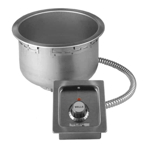
BUILT-IN ROUND WELL
(Insulated & Non-Insulated)
SS8T, TU TD, TD6
SS10ULT, ULTD
SS8TDUIAF, CIAF
SS10TDUIAF, CIAF
WARMERS
with
THERMOSTAT
CONTROL
MODELS
SS4ULT, ULTD
SS8ULT, ULTD
SS10T, TD
(Auto-Fill)
Includes
INSTALLATION
USE & CARE
EXPLODED VIEW
PARTS LIST
WIRING DIAGRAM
011D
03/18
Advertisement
Table of Contents

Related Manuals for Wells SS4 Series


Summary of Contents for Wells SS4 Series
- Page 1 Additional manuals are available from your WELLS DEALER. THIS MANUAL MUST BE READ AND UNDERSTOOD BY ALL PERSONS USING OR INSTALLING THIS APPLIANCE. Contact your WELLS DEALER if you have any questions concerning installation, operation or maintenance of this equipment.
- Page 2 Wells’ discretion have the parts replaced or codes, including incorrect gas or electrical connection. Wells is not liable repaired by Wells or a Wells-authorized service agency.
-
Page 3: Table Of Contents
ACCESSORIES LIST CUSTOMER SERVICE DATA INTRODUCTION Thank You for purchasing this Wells appliance. Proper installation, professional operation and consistent maintenance of this appliance will ensure that it gives you the very best performance and a long, economical service life. This manual contains the information needed to properly install this appliance, and to use and care for the appliance in a manner which will ensure its optimum performance. -
Page 4: Features & Operating Controls
FEATURES & OPERATING CONTROLS A. THERMOSTAT On THERMOSTATICALLY CONTROLLED warmers, power is applied to the heating element according to the control knob position and the actual temperature at the temperature sensing thermobulb. INDICATOR LIGHT The desired temperature is controlled by rotating the TEMPERATURE CONTROL KNOB. -
Page 5: Precautions & General Information
Do not operate this appliance if the control panel is damaged. Call read and followed. Damage your Authorized Wells Service Agent for service. to the appliance may result The technical content of this manual, including any wiring diagrams,... -
Page 6: Installation
INSTALLATION NOTE: DO NOT discard UNPACKING & INSPECTION the carton or other packing Carefully remove the appliance from the carton. Remove all materials until you have protective plastic film, packing materials and accessories from the inspected the appliance for Appliance before connecting electrical power or otherwise performing hidden damage and tested it any installation procedure. - Page 7 INSTALLATION continued 4. For “top-mounted” warmers (i.e. warmers mounted from above the counter top): a. Verify that provided sealants are applied to the underside of the warmer top flange prior to setting the unit into the cutout. b. After installation, verify that the tabs on the Wellsloks are turned out to lock the warmer into the counter c.
- Page 8 These units will contain water with AUTOFILL units require a drain valve (not supplied by Wells) to be temperatures in excess of installed in order to operate correctly. 180°F and localized metal...
-
Page 9: Operation
SHOCK HAZARD Wells Manufacturing recommends operating WET for consistent food heating. DO NOT splash or pour water If your wet-operation warmer is allowed to run dry, turn it OFF and onto control panel or wiring. - Page 10 OPERATION continued CAUTION: AUTOFILL WARMERS HOT SURFACE Autofill warmers sense water level by a sensor placed at the proper level. For manifolded autofill warmers, the water level sensor / fill tube is in one pan only. Exposed surfaces can be hot to the touch and may cause Water fills the pan through an inlet tube.
-
Page 11: Maintenance Instructions
Never use metal implements, wire brushes, abrasive scratch pads or steel wool to clean stainless steel. Warmer pans, insets and other vessels are subject to a harsher environment. Wells Manufacturing uses an very high quality stainless steel (#304DDQ) for our food warmer pans. -
Page 12: Cleaning Instructions
Contact your Authorized Wells Service Agency to inspect warmer if water or grease contamination is suspected. Close drain valve. Add proper amount of warm water. Turn control... - Page 13 CLEANING INSTRUCTIONS CAUTION: WEEKLY CLEANING INSTRUCTIONS CHEMICAL BURN PREPARATIONS: Remove any insets, pans and/or adapter tops. HAZARD Drain or remove water from well if used for wet Delimng chemicals may be operation. caustic. Wear appropriate personal protective equipment. FREQUENCY: Weekly, or whenever lime or scale is seen Follow cleaner manufacturer’s accumulating on the sides of the warmer pans.
-
Page 14: Troubleshooting Suggestions
There are no user-serviceable components in this appliance. In all instances of damage or malfunction, contact your Authorized Wells Service Agency for repairs. WIRING DIAGRAM - AUTOFILL WIRING DIAGRAM FOR SS4, 8, 10 ROUND WARMERS W/ AUTOFILL NOM. -
Page 15: Wiring Diagram
WIRING DIAGRAM WIRING DIAGRAM FOR SS4ULT(C); SS8ULT(C); SS10ULT(C) 120 OR 208/240V SINGLE PHASE WITH OR WITHOUT OPTIONAL POWER CORD HEATER ELEMENT 16 GA. NICKEL STRANDED APPLIANCE WIRE. GREEN BLACK THERMOSTAT WHITE PILOT LIGHT OPTIONAL POWER CORD (120V, 208V, 240V) GREEN THERMOSTAT NOM. -
Page 16: Exploded View & Parts List
EXPLODED VIEW & PARTS LIST SS8T and SS10T with & without Drain Model: SS4T, SS8T & SS10T (w & w/o Drain) IL1904 Rev. F 4/08/15 SS4TU, SS8TU & SS10TU (w & w/o Drain) - Page 17 PARTS LIST SS4T, SS8T & SS10T units with & without drain April 08, 2015, Rev B Model: SS4T, SS8T, SS10T (Insulated & non-insulated) with & without Drian Fig No Part No. Description Application 2V-Z17446 Drain Screen Drain Units WS-63527 SS4ULT WS-50391 Pot Assembly SS8ULT, SS8T...
- Page 18 PARTS LIST SS4T, SS8T & SS10T units with & without drain April 08, 2015, Rev B Model: SS4T, SS8T, SS10T (Insulated & non-insulated) with & without Drian Fig No Part No. Description Application THERMOSTAT MOUNTING P2-40843 BRKT I7-Z12221 CONTROL PANEL 2J-35687 LIGHT SIGNAL 2R-40498...
- Page 19 EXPLODED VIEW AUTO-FILL SEE DETAIL SK2697, Rev. A , 4/09/15 Model: SS10TDUIAF (w Drain & AUTO-FILL)
- Page 20 EXPLODED VIEW AUTO-FILL: Detail A 33 34 DETAIL SK2893 Rev. - , 4/09/15 Model: SS10TDUIAF (w Drain & AUTO-FILL) CONTROL PANEL ASSEMBLY...
-
Page 21: Auto-Fill Units
PARTS LIST AUTO-FILL SS8TDUIAF & SS10TDIAF units with drain & Autofill April 08, 2015, Rev B Model: SS8TDUIAF, CIAF & SS10TDUIAF, CIAF AUTO-FILL Fig No. Part No Quantity Description Application 2V-Z17446 DRAIN SCREEN SS10TDUIAF P2-WL0453 ASM-SENSOR WATER LEVEL-AF P2-WL0446 POT ASM-SS10 AUTOFILL SS10TDUIAF P2-WL0447 POT ASM-SS8 AUTOFILL... - Page 22 PARTS LIST AUTO-FILL continued SS8TDUIAF & SS10TDIAF units with drain & Autofill April 08, 2015, Rev B Model: SS8TDUIAF, CIAF & SS10TDUIAF, CIAF AUTO-FILL Fig No. Part No Quantity Description Application 2E-306865 CONTROL LIQ LEVEL 208/240 208/240V 2E-46604 CONTROL LIQ LEVEL 120V 120V 2I-40034 GROMMET SCREW T4...
-
Page 23: Customer Service Data
4 QT. ROUND INSET w/ lid WS-20774 replacement parts, contact 7 QT. ROUND INSET w/ lid WS-20587 your Wells authorized service 11 QT. ROUND INSET w/ lid WS-20908 agency, or call: 11 QT. ROUND INSET w/ hinged lid WS-21057... - Page 24 WELLS MANUFACTURING 265 Hobson Street, Smithville, Tennessee 37166 telephone: 314-678-6314 fax: 314-781-2714 www.wells-mfg.com...