Table of Contents
Advertisement
Quick Links
Advertisement
Table of Contents

Related Manuals for Schwinn 9-7310


Summary of Contents for Schwinn 9-7310
- Page 1 Core Health & Fitness Schwinn® SC Power SERVICE MANUAL...
-
Page 2: Table Of Contents
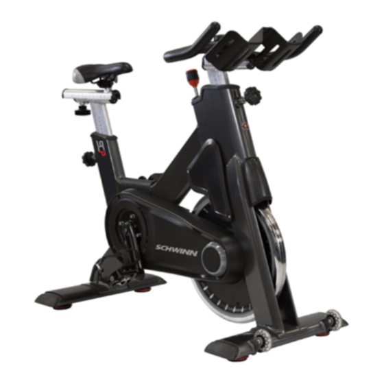
TABLE OF CONTENTS Click any text to jump to section PRODUCT SPOTLIGHT ............................. 3 OTHER MANUALS ............................. 4 ACCESSORIES ............................. 5 ..................5 Cranks & Pedals REPLACEMENT PROCEDURES ............................. 6 ..................6 Shroud Removal ..................7 Belt Tension & Replacement Pedal Replacement (Morse Taper) ..................10 Adjusting Leveling Feet ..................11... - Page 3 PRODUCT SPOTLIGHT 9-7310 S.C.™ Power 9-7310 S.C.™ Power Custom Overall Weight Width Length Height User Weight 120 lbs (54 kg) 21” (53 cm) 55” (140 cm) 46” (117 cm) 0-350 lbs (0-159 kgs) Product Conformity • EN957-1 (S,H) • EN957-10 (S,H) •...
- Page 4 OTHER MANUALS Click the links below to load the related complete manuals from our support website. Safety warnings and warranty information specific to each unit are located in their respective own- er’s manuals. Manuals Install Owner’s AC Performance (100175) AC Performance (9-7320) AC Performance Plus AC Sport SC Power...
- Page 5 ACCESSORIES Standard Schwinn pedals have threaded shafts that connect to the crank arms. The right pedal is right-hand threaded while the left pedal is reverse threaded, meaning you turn to the left to tight- en and right to loosen. For pictures of all different Schwinn pedals, see document...
-
Page 6: Shroud Removal
REPLACEMENT PROCEDURES Shroud Removal Remove the rubber chainguard cap. Remove the screws from the user right chainguard (inset). Use a Phillips screw driver and 5mm hex key to remove the screws securing the user left Chainguard to the bike. Rotate the chainguard downward to remove Page 6... -
Page 7: Belt Tension & Replacement
Belt Tension & Replacement Remove the rubber chainguard cap. Remove the screws from the user right chainguard (inset). Use a Phillips screw driver and 5mm hex key to remove the screws securing the user left Chainguard to the bike. Rotate the chainguard downward to remove Remove the rubber cap from the user left side. - Page 8 Use a 13mm open-ended wrench to loosen the belt idler tension spring. Use a 3mm allen key to remove the screw connecting the idler to the tensioner arm. Carefully walk the belt off of the tensioner pulley then walk the belt off of the crank pulley. Use a 3mm allen key and a 13mm open-ended wrench to remove the two (2) screws and nuts connecting the cross brace to the front right fork.
- Page 9 Walk the generator belt off the right-side flywheel pulley then rotate the flywheel back and down to the remove the flywheel from the frame. NOTE: Take care as the flywheel is heavy. Push the front of the cross brace away from right front fork to create a gap then slide the old belt through the gap.
-
Page 10: Pedal Replacement (Morse Taper)
Pedal Replacement (Morse Taper) Use an 8mm allen key to remove the pedal bolt. NOTE: The crank arm and pedal are shown detached from the bike for clarity only, it is not necessary to remove the crank arm. Thread a crank puller tool with the smaller 11mm tip into the crank arm, then use the tool to push the pedal out of the crank arm. -
Page 11: Adjusting Leveling Feet
Adjusting Leveling Feet Ensure the bike is level by adjusting all four leveling feet. Turn the leveling foot clockwise to lower the bike and counter-clockwise to raise the bike. When leveled properly, the bike should not wobble or lean to any one side. Page 11... -
Page 12: Crank Arm Replacement
Crank Arm Replacement Remove the rubber chainguard cap. Remove the screws from the user right chainguard (inset). Use a Phillips screw driver and 5mm hex key to remove the screws securing the user left Chainguard to the bike. Rotate the chainguard downward to remove Walk the belt/chain off of the bike unless replacing the user left side crank arm only. - Page 13 Thread a crank puller tool with the larger 16.5mm tip into the crank arm, then use the tool to pull the crank arm off the bottom bracket. Repeat on user left. Install the user right crank arm by aligning the splines in the crank arm (blue) to the bottom bracket shaft (yellow).
-
Page 14: 4Iiii Crank Replacement
4iiii Crank Replacement Use an 8mm allen key to remove the crank bolt. Thread a crank puller tool with the larger 16.5mm tip into the crank arm, then use the tool to pull the crank arm off the bottom bracket. Ensure the opposite side crank arm is at the 12 o’clock position then push the new crank arm onto the bottom bracket at the 6 o’clock position. - Page 15 Install the pedal into the crank arm then use a torque wrench and a 8mm allen socket to torque to the pedal bolt according to the specifications below: • Threaded Pedal: 25-30 ft-lb (34-40 Nm) • Morse Taper Pedal: 33 -37 ft-lb (45-50 Nm) NOTE: The pedal MUST be torqued to the above specifications otherwise a failure of the pedal may occur.
-
Page 16: Pairing & Calibrating The 4Iiii Crank
Pairing & Calibrating the 4iiii Crank Press and hold “STAGE” and “AVG/MAX” for 3-5 seconds to access the service menu. Use “AVG/MAX” to scroll until “SENSOR TYPE” is displayed then push the backlight button to access the sensor menu. Ensure that “4iiii” is displayed as the sensor type. If the sensor type is set to “Echelon 2”... -
Page 17: Bottom Bracket Replacement
Bottom Bracket Replacement Remove the rubber chainguard cap. Remove the screws from the user right chainguard (inset). Use a Phillips screw driver and 5mm hex key to remove the screws securing the user left Chainguard to the bike. Rotate the chainguard downward to remove Walk the belt/chain off of the bike unless replacing the user left side crank arm only. - Page 18 Thread a crank puller tool with the larger 16.5mm tip into the crank arm, then use the tool to pull the crank arm off the bottom bracket. Repeat on user left. Use a 35mm open-ended wrench to remove the bottom bracket retaining nut.
- Page 19 50 ft-lb / 68 Tighten the bottom bracket retaining nut to Page 19...
-
Page 20: Brake Rod Replacement
Brake Rod Replacement Use a 5mm hex key to remove the screws securing the right side sweatguard to the bike. Remove the retaining screw (blue) from the top cap, then pull out the front pop pin (blue), then pull upwards on the brake top cap (yellow) to remove it. -
Page 21: Brake Replacement
Brake Replacement Use a 5mm hex key to remove the screws securing the right side sweatguard to the bike. Remove the retaining screw (blue) from the top cap, then pull out the front pop pin (blue), then pull upwards on the brake top cap (yellow) to remove it. - Page 22 Using a phillips screwdriver, remove the brake bracket cov- er from the front of the bike (blue) After removing the brake bracket cover, use a #3 hex key to remove the screws securing the brake bracket to the frame (yellow) Remove the brake assembly from the bike.
-
Page 23: Other Replacement Procedures
Other Replacement Procedures Procedure Link Note Replacing the battery on a SC Power 637-8617 Page 23... -
Page 24: Power & Mechanical Issues
TROUBLESHOOTING This page lists out all procedures available for Schwinn bikes. Use the icon to open the procedure in a new browser window. Internet connection is required. Power & Mechanical Issues Link Note Procedure No power on an Echelon 2G... - Page 25 © 2018 CORE HEALTH & FITNESS, LLC PART NUMBER 637-8647, REV A...