Schwinn MPower Echelon2 Service Manual
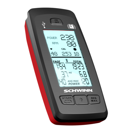
Console
Hide thumbs
Also See for MPower Echelon2:
- Installation manual (34 pages) ,
- Owner's manual (28 pages) ,
- Assembly manual (14 pages)
Advertisement
Advertisement
Table of Contents

Related Manuals for Schwinn MPower Echelon2


Summary of Contents for Schwinn MPower Echelon2
- Page 1 Core Health & Fitness Schwinn Echelon2 SERVICE MANUAL...
-
Page 2: Tools Required
The degree of management depends on the user's ability to rec- ognize and prevent danger to third parties during the exercise movement. Tools Required The tool list below is needed to repair and perform preventative maintenance on all Schwinn bikes. • PEDAL WRENCH •... - Page 3 Echelon2 Console What’s in the Box General Features/Functions Installation of the Schwinn® Echelon2 Console System Zeropoint Calibration Procedure Echelon2 Post-Install Checklist Power Validation Table Menu Map Wiring Diagram and Signal Flow Preventative Maintenance Troubleshooting and Service Console Not Displaying RPMs...
-
Page 4: What's In The Box
What’s in the Box? SCHWINN® Echelon2 (Part #740-8727) Package includes components listed below Index Part Number Description 740-8727 SCHWINN® Echelon2 110-3640 SCREW, PHP, M4x0.7x10, SS 110-3641 SCW-BHCS M5x0.8x14 SS 110-3642 SCREW, M3X0.5,12mm, SHC, HK, SS,GR 8.8 110-3643 SCREW, M3X0.5,6mm,RHM,PH,SS 140-3585... - Page 5 SCHWINN® Echelon2 Power Upgrade Kit (Part #740-8730) Package includes components listed below Index Part Number DESCRIPTION 740-8730 SCHWINN® Echelon2 POWER UPGRADE 110-3644 SCREW, M4X0.7X14, BHSC,HE,SS 740-8607 CALIBRATION TOOL, ZERO POINT, ACPP 740-8730-005 POWER SENSOR UPGRAGE PACKAGING 740-8931 POWER UPGRADE CABLE, RJ45...
- Page 6 SCHWINN® Echelon2 External Wire Kit (Part #740-8875) Package includes components listed below Index Part Number Description 740-8875 KIT, EXTERNAL WIRE, Echelon2 740-8875_001 EXTERNAL CABLE COVER ASSY 740-8875_005 CABLE CLAMP Page 6...
- Page 7 Echelon2 Features and Functionality The Echelon2 provides riders with real-time user metrics that can be used to improve the current and future workouts. Watts, time, kcal, distance, RPMs, speed, distance, and heartrate are displayed on an intuitive display that allows for ease of use during high intensity rides.
- Page 8 118” (3 m) during Workout Mode. If you have a compatible paired ANT+ Sport Watch and ANT+ HRM, the console links with the Sport Watch and reads the heart rate data from it, if the watch is compatible. The Schwinn console uses the ANT+ Fitness Profile. Visit www.thisisant.com for a directory of compatible devices •...
-
Page 9: Heart Rate
Power The power display field shows the Power in Watts that you are producing at the current resistance level (1 horsepower = 746 Watts). Power data only shows if there is a power sensor installed on the bike. The RPM display field shows the current pedal revolutions per minute (RPM). Heart Rate The Heart Rate display field shows the heart rate in beats per minute (BPM) from the heart rate monitor (HRM). -
Page 10: Battery Level
Please consult with your physician prior to engaging in any strenuous physical activity. Schwinn does not warranty the heart rate system performance on this product, as the heart rate system performance various based on a user’s physiology, fitness level, age, method of use, and other factors. -
Page 11: Pause Mode
The console receives data from the bike’s sensors and uses the data to calculate workout results. RPM Sensor: The Schwinn® console comes with a RPM sensor for the bike. This sensor transmits data from the flywheel to the power sensor and the console. - Page 12 Zeropoint Current Angle Quick Check Software V1.7 adds a new feature that allows users to quickly check the current angle of the Zeropoint Calibration from the main Ride menu. The enables riders to quickly check to verify the sensor is still calibrated without having to navigate through the service menu.
- Page 13 Installation of the Schwinn® Echelon2 Console System Tools Required: Phillips Screwdriver 2.5mm Allen Key 3mm Allen Key Soft-jaw Pliers (pliers with protective rubber or plastic covering jaws) WARNING: Do not use power tools for any part of the installation of the console, power sensor, or related com- ponents.
- Page 14 Tighten the screws using the 3mm hex key Slide the console onto the bracket. Insert the M3 x 6mm pan head screw and tighten with the screw driver Prior to installing the upper conduit, clean head tube with isopropyl alcohol. Allow to air dry. Peel off backing adhesive and align duct part number 740- 8875-001 to forward edge and lower edge of the frame tube.
- Page 15 Snap the outer part of the cable duct onto the base with the cable inside Using a philips screw driver, remove the sweat guard (Do not use a power drill in removing and re-installing) Route the cable through the sweat guard Page 15...
- Page 16 Re-mount the sweat guard Plug the console cable RJ45 connector into the console then slide the grommet of the cable into the slot on the connector protective cap as shown Attach the protective cap to the bracket using the two (2) M3 x 12mm socket head cap screws, and tighten with the 2.5mm hex key Page 16...
- Page 17 Attach the RPM sensor adapter to the RPM sensor using the M3 x 6mm Philips Pan Head Screw Unscrew the M3 x 6mm Philips Pan Head screw holding the RPM sensor cover on and remove it Page 17...
- Page 18 Plug the RPM sensor cable 2-pin connector into the RPM sensor connector and slide the cable grommet into the slot in the RPM sensor housing Reinstall the RPM sensor cover into the housing, and reinstall the M3 x 6mm Philips Pan Head screw Page 18...
- Page 19 Remove the top and bottom screw from the front of the chain guard Position the RPM sensor as shown and reinstall the two chain guard screws. The RPM sensor should be about 2 - 3mm away from the flywheel, or about the width of a credit card. If the RPM sensor is too close, it will rub against the sensor magnet that is embedded in the flywheel.
- Page 20 Route the wire inside the conduit and snap the conduit outer cover on to the base Page 20...
- Page 21 AC Performance Plus™ and AC Performance Plus Carbon Blue™ Installation NOTE: If installing the console with the optional power upgrade at the same time as the console, review the in- structions in the section “Optional Power Upgrade Kit Installation on AC™ Performance Plus” before proceeding with the steps in this section.
- Page 22 Place the handlebar back on the bike. Feed the end of the cable out of the end of the head tube. Wear heavy-duty protective gloves when pulling the end of the cable out of the head tube as there may be sharp edges inside the head tube Mount the console bracket using the three (3) M4 x 10mm Philips Pan Head screws, and tighten the...
- Page 23 Plug the console cable RJ45 connector into the console then slide the grommet of the cable into the slot on the connector protective cap as shown Attach the protective cap to the bracket using the two (2) M3 x 12mm socket head cap screws, and tighten with the 2.5mm hex key Install the cosmetic cap using a M5 x 14mm BHCS Page 23...
- Page 24 Using a Philips screw driver, remove the sweat guard (Do not use a power drill in removing and re-installing). Route the cable through the sweat guard Unscrew the M3 x 6mm Philips Pan Head screw holding the RPM sensor cover on and remove it Page 24...
- Page 25 Plug the RPM sensor cable 2-pin connector into the RPM sensor connector and slide the cable grommet into the slot in the RPM sensor housing Reinstall the RPM sensor cover into the housing, and reinstall the M3 x 6mm Philips Pan Head screw Page 25...
- Page 26 Remove the top and bottom screw from the front of the chain guard Position the RPM sensor as shown and reinstall the two chain guard screws. The RPM sensor should be about 2 - 3mm away from the fly- wheel, or about the width of a credit card. If the RPM sensor is too close, it will rub against the sensor magnet that is embedded in the flywheel.
- Page 27 Secure the cable inside the two saddle clamps as shown Page 27...
- Page 28 Power Upgrade Kit Installation for AC Sport and AC Performance Bikes NOTE: When installing the power upgrade kit, do not use the console-to-RPM sensor cable (1.11: 740-8928) from the console kit. This cable is not used when installing the power upgrade kit. Use the console-to-power cable (1.4: 740-8931) in the power kit to connect the console to the power sensor.
- Page 29 Position rubber boot with magnet (magnet assem- bly) so that the hex pattern of the boot lines up exactly with the hex nut on the resistance mecha- nism. NOTE: As of July 2016, the sensor magnet will be mounted during production at the factory. Slide boot onto hex nut and ensure that boot sits in contact with the black plate of the resistance mechanism...
- Page 30 Plug console cable into the RJ45 connector at the front of the sensor, and the RPM cable into the 2-pin connector on the underside of the power sensor. Slide each cable’s grommet into their re- spective slots in the power sensor case Attach sensor case to the resistance mechanism using the M4 x 6mm button head screws.
- Page 31 Power Upgrade Kit Installation for AC Performance Plus and Carbon Blue Bikes NOTE: When installing the power upgrade kit, do not use the console-to-RPM sensor cable (1.11: 740-8928) from the console kit. This cable is not used when installing the power upgrade kit. Use the console-to-power cable (1.4: 740-8931) in the power kit to connect the console to the power sensor.
- Page 32 Position rubber boot with magnet (magnet assembly) so that the hex pattern of the boot lines up with the hex nut on the resistance mechanism. Note: As of July 2016, the sensor magnet will be mounted during production at the factory. Note: If the bike serial number is XXXXXXDAY1642XXXX or later, an updated bolt and magnet assembly will be installed at the fac- tory.
- Page 33 Plug console cable into the RJ45 connector, and the RPM cable into the 2-pin connector on the power sensor. Slide each cable’s grommet into their respective slots in the power sensor case. Attach sensor case to the resistance mechanism using the M4 x 6mm button head screws.
- Page 34 Zeropoint Calibration Procedure The Zeropoint Calibration Procedure ensures that the console will display the rider status. It sets the zeropoint for the power sensor and allows the console to use a formula, with the RPMs and the angle of the brake as variables, to provide calories, power, and RPMs.
- Page 35 Follow the on-screen instructions; place the calibration tool on the flywheel, rotate back until the tool fits between the mag- nets of the brake assembly, and then press the LIGHT button. Turn the brake knob clockwise until the brake mechanism makes contact with the calibration tool and press the LIGHT button.
- Page 36 At this point calibration is done. Exit the service menu and remove the tool from the flywheel (keep for future use, the tool can be stored under the cosmetic bracket cover for safe keep- ing) Page 36...
- Page 37 Echelon2 Post-Install Checklist Ensure all wiring is routed properly and does not interfere with any moving parts Verify the RPM sensor is 2mm – 3mm away from flywheel. Before mounting the Echelon2 power sensor to the magnetic brake, ensure the rubber magnet cap is installed over the nut of the brake assembly if applicable.
- Page 38 NOTE: The power validation test will work for any gear/RPM combination in the table, so not all combinations need to be used for the validation test. Page 38...
- Page 39 NOTE: The power validation test will work for any gear/RPM combination in the table, so not all combinations need to be used for the validation test. Page 39...
- Page 40 Page 40...
- Page 41 Service Mode Service mode may be entered immediately after powering on the console, or when the console is in Pause mode (Pause mode is indicated by flashing digits on the screen). Service mode cannot be entered during Ride mode. To enter Service mode, press and hold the “STAGE”...
- Page 42 Service Menu Maps Page 42...
- Page 43 Page 43...
- Page 44 Page 44...
- Page 45 Page 45...
- Page 46 Page 46...
- Page 47 System Settings Defined Carbon Blue This setting is used to distinguish between Carbon Blue bike with a belt and bikes with a chain. The default setting is ON. Leave this setting set to ON for Carbon Blue models. On models with chain, set it to OFF. Gear This is an optional setting that enables the console to display a gear number that corresponds to the level of resistance.
-
Page 48: Preventative Maintenance
Preventative Maintenance Before every ride: • Check to ensure no wires are damaged or disconnected. • Check to ensure all wires are secure and not touching any moving part of the bike. After every ride: • Wipe down the console. •... -
Page 49: Wiring Diagrams
Wiring Diagrams Echelon2 with RPM Sensor ONLY Echelon2 with RPM Sensor AND Power Sensor: Page 49... -
Page 50: Troubleshooting
Troubleshooting RPM Troubleshooting Leaderboard not Connecting No Power to Console Device Pairing No Power or Calorie Reading Readings Inconsistent Page 50... - Page 51 RPM Troubleshooting Echelon & Echelon 2 Doc. #637-4419 The purpose of the document is to help troubleshoot for intermittent or no RPM readings on the Echelon 2 console. Page 51...
- Page 52 Use a steel paperclip and run it around the inside of the flywheel about 1 inch away from the edge of the Schwinn Star decal. As shown below, if the magnet is present, the steel paperclip should stick. Page 52...
- Page 53 • Testing continuity on the RPM sensor: Tools Required: Multimeter Phillips Screwdriver • Remove the RPM sensor from the bike using a phillips screwdriver then use a multimeter to Fig 1. check the continuity on the RPM sensor (Fig. 1) while waving a magnet ~1-2mm from the front of the sensor (Fig.
- Page 54 Not Connecting to Leaderboard System Echelon & Echelon 2 Doc. #637-4456 The purpose of this document is to help troubleshoot connectivity issues when pairing the Echelon 2 console to a lead- erboard system such as Performance IQ (PIQ). Page 54...
- Page 55 Checking current firmware version: Press the ON/OFF button at the top of the display Push and hold the STAGE and AVG/MAX buttons at the same time until “Carbon Blue” appears on the display, this is the landing screen for the service menu. Press the AVG/MAX button to scroll through the service menu until “SYSTEM”...
- Page 56 Checking ID number: Enter Service Mode again by pressing and holding the STAGE and AVG/MAX buttons. Scroll to the “SYSTEM” menu by pressing the AVG/MAX button. Then press the LIGHT button to enter the system sub-menu. Press the AVG/MAX button to scroll in the system sub-menu until “SERIALNUM” is displayed. The number dis- played below “SERIALNUM”...
- Page 57 No Power to Console Echelon & Echelon2 Doc. #637-4454 This purpose of this document is to help troubleshoot and diagnose for power issues on the Echelon 2 console. Power Button Correct Battery Orientation Page 57...
- Page 58 Heartrate or Fitness Tracker Not Pairing Echelon 2 Doc. #637-4455 The purpose of this document is to help troubleshoot for heartrate monitors or fitness trackers not pairing to the Eche- lon 2 console. Page 58...
- Page 59 • To check if the device that is attempting to be paired is compatible with the Echelon 2, please visit www.thisisant.com/directory/mpower-echelon2-cosole/ • Device pairing distances: ANT+ watch --link to the console. Move the watch to 2”-4” (5-10 cm) or less from the ANT+ Link Here icon on the console and hold it there until proximity linking is complete.
- Page 60 No Power or Calorie Reading Echelon 2 Doc. #637-4457 The purpose of this document is to help troubleshoot when no power or calorie readings are displayed on the Echelon 2 console. Please note that the power sensor is required in order for the console to display power or calories. Page 60...
- Page 61 Checking current firmware version: Press the ON/OFF button at the top of the display Push and hold the STAGE and AVG/MAX buttons at the same time until “Carbon Blue” appears on the display, this is the landing screen for the service menu. Press the AVG/MAX button to scroll through the service menu until “SYSTEM”...
- Page 62 Performing Zeropoint calibration: Power on the console Enter the service menu by holding down the STAGE and AVG/MAX buttons together for about 4-6 seconds. Once in the service menu, use the AVG/MAX button to scroll to the CALBRATE menu. Press and release the LIGHT button to enter the menu Scroll to CALIBRATE ZEROPOINT option and press the LIGHT button.
- Page 63 Follow the on-screen instructions; place the calibration tool on the flywheel, rotate back until the tool fits between the magnets of the brake assembly, and then press the LIGHT button. Turn the brake knob clockwise until the brake mechanism makes contact with the calibration tool and press the LIGHT button.
- Page 64 Once the calibration passes, go to CALIBRATE CURRENT ANGLE and verify the angle is 0.0 (+/- 0.1 degrees) Occasionally, the calibration process does not correctly set the angle on the first try. If the angle reads anything other than 0.0 (+/- 0.1 degrees), perform the calibration again until the CURRENT ANGLE reads 0.0 (+/- 0.1 degrees).
- Page 65 Checking to see if magnet cap is rotating: Remove the use right side sweat guard using a phillips screwdriver. Remove the power sensor using a 3/32”allen key. Attempt to turn the magnet cap located over the nut of the main brake carriage bolt as shown below. If magnet cap is rotating and 740-9098 “F-Screw ASSY, W-Magnet, M10 Shoulder, AC Bike Brake”...
- Page 66 Using a 8mm allen key and a 17mm socket, remove the hardware that secures the brake assembly to the frame Insert the bolt component of 740-9098 from the user right hand side to re-secure the brake assembly to the frame. Note that you may need to loosen the set screw inside the bolt using a 2mm allen key in order to insert the bolt into the brake and/or frame.
- Page 67 Power or Calorie Readings High/Low/Inconsistent Echelon 2 Doc. #637-4458 The purpose of the document is to help troubleshoot low/high/inconsistent power or calorie readings on the Echelon 2 console. Page 67...
- Page 68 Checking current firmware version: Press the ON/OFF button at the top of the display Push and hold the STAGE and AVG/MAX buttons at the same time until “Carbon Blue” appears on the display, this is the landing screen for the service menu. Press the AVG/MAX button to scroll through the service menu until “SYSTEM”...
- Page 69 Performing Zeropoint calibration: Power on the console Enter the service menu by holding down the STAGE and AVG/MAX buttons together for about 4-6 seconds. Once in the service menu, use the AVG/MAX button to scroll to the CALBRATE menu. Press and release the LIGHT button to enter the menu Scroll to CALIBRATE ZEROPOINT option and press the LIGHT button.
- Page 70 Follow the on-screen instructions; place the calibration tool on the flywheel, rotate back until the tool fits between the magnets of the brake assembly, and then press the LIGHT button. Turn the brake knob clockwise until the brake mechanism makes contact with the calibration tool and press the LIGHT button.
- Page 71 Once the calibration passes, go to CALIBRATE CURRENT ANGLE and verify the angle is 0.0 (+/- 0.1 degrees) Occasionally, the calibration process does not correctly set the angle on the first try. If the angle reads anything other than 0.0 (+/- 0.1 degrees), perform the calibration again until the CURRENT ANGLE reads 0.0 (+/- 0.1 degrees).
- Page 72 Checking magnet gap: In order to achieve consistent power output between multiple bikes, it is very important that the gap between the magnets on the resistance mechanism is correct and consistent between bikes. The gap is set by the factory when the bikes are assembled;...
- Page 73 To adjust the magnet gap, carefully place a pair of soft-jaw pliers around the outside of the resis- tance mechanism plates, and squeeze. Make small adjustments at a time and check the gap with the tool fit—the fit should be a slip fit with no side-to-side play. Also ensure that the flywheel remains centered between the magnets.
- Page 74 FAQs How is the Echelon2 console and power upgrade different from the Echelon? • The power sensor has been replaced with a new sensor that is more stable and more accurate than the previous power sensor, and consumes less energy. •...
- Page 75 How do I record my ride data using a USB drive? • Insert a USB 2.0 drive into the USB port in the top of Echelon2 console before beginning the ride. Once the ride is finished, press and hold the AVG/MAX button on the console to end the ride. The console will then go into a ride summary screen and will then proceed to export the data from the ride to the USB drive.
- Page 76 Why do I have to calibrate the Echelon2 console monthly? • The Echelon2 console is the most stable and reliable group cycle computer that Schwinn has ever produced. If you are encountering inaccurate watts/power/calories ensure that the console firmware is updated to V1.6 or greater;...
- Page 77 In the FILE SYSTEM pull-down menu, choose FAT32. All data on the USB stick will be deleted and the drive will now use the FAT32 system and should work with the console. Transfer the newest software onto the newly formatted USB stick for use in updating the console.
- Page 78 How do I assign a new console ID number? Enter Service Mode again by pressing and holding the STAGE and AVG/MAX buttons. Scroll to the SYSTEM menu by pressing the AVG/MAX button. Then press the LIGHT button to enter the SYSTEM menu.