Metrologic Eclipse MS5100 Series Installation And User Manual
Hide thumbs
Also See for Eclipse MS5100 Series:
- Installation and user manual (40 pages) ,
- Installation and user manual (52 pages) ,
- Installation and user manual (52 pages)
Table of Contents
Advertisement
Quick Links
Advertisement
Table of Contents

Related Manuals for Metrologic Eclipse MS5100 Series


Summary of Contents for Metrologic Eclipse MS5100 Series
- Page 3 Copyright © 2004 by Metrologic Instruments, Inc. All rights reserved. No part of this work may be reproduced, transmitted, or stored in any form or by any means without prior written consent, except by reviewer, who may quote brief passages in a review, or provided for in the Copyright Act of 1976.
-
Page 4: Table Of Contents
ABLE OF ONTENTS Introduction......................1 Scanner and Accessories..................2 Operation Test...................... 4 Installing the Scanner to the Host System............5 The PowerLink Cable ................... 9 Disconnecting....................9 Connecting ....................... 9 Scanner Parts..................... 10 The MS5145 Eclipse™ Series................11 ® How to Use CodeGate and the Manual Activation Mode...... -
Page 5: Introduction
(CodeSense™ Mode), the laser beam automatically switches to scan mode and activates CodeGate to ensure high-speed scanning and accuracy. Metrologic has included many standard features such as: user programmable ® ®... -
Page 6: Scanner And Accessories
Keyboard Wedge PowerLink Cable with Adapter Cable, 55-55002A-3 black 55-55020A-3 Stand Alone Keyboard Wedge PowerLink Cable, black Other items may be ordered for the specific protocol being used. To order additional items, contact the dealer, distributor or call Metrologic’s Customer Service Department at 1-800-ID-METRO or 1-800-436-3876. - Page 7 MVC converter cable series and the host connections available. 46-46633 Countertop Stand Other items may be ordered for the specific protocol being used. To order additional items, contact the dealer, distributor or call Metrologic’s Customer Service Department at 1-800-ID-METRO or 1-800-436-3876.
-
Page 8: Operation Test
PERATIONAL Connect the 10-pin RJ45 male connector into the jack on the Eclipse. You will hear a ‘click’ when the connection is made. Connect the L-shaped plug of the power supply into the power jack on the PowerLink cable. Connect the power supply into an AC outlet. -
Page 9: Installing The Scanner To The Host System
NSTALLING THE CANNER TO THE YSTEM MS5145-00/9/11/14/41 Turn off the host system. Connect the 10-pin RJ45 male connector into the jack on the Eclipse. You will hear a ‘click’ when the connection is made. If the scanner is receiving power from the host system, skip to step #5. - Page 10 Not all computers supply the same current through the keyboard port, explaining why a scanner may work on one computer and not another. Contact a Metrologic Customer Service Representative if you require an external power supply. Caution: To maintain compliance with applicable standards, all circuits connected to the scanner must meet the requirements for SELV (Safety Extra Low Voltage) according to EN 60950.
- Page 11 Not all computers supply the same current through the keyboard port, explaining why a scanner would work on one computer and not another. Contact a Metrologic Customer Service Representative if you require an external power supply. Caution: To maintain compliance with applicable standards, all circuits connected to the scanner must meet the requirements for SELV (Safety Extra Low Voltage) according to EN 60950.
- Page 12 NSTALLING THE CANNER YSTEM USB: HID/POS USB MS5145-38 PEED USB MS5145-40 PEED Turn off the host system. Connect the 10-pin RJ45 male connector of the USB cable into the jack on the Eclipse. You will hear a ‘click’ when the connection is made.
-
Page 13: The Powerlink Cable
OWER ABLE Disconnecting the PowerLink Cable Before removing the cable from the scanner, Metrologic recommends that the power on the host system is off and the power supply has been disconnected from the PowerLink cable. Figure 8. Locate the small ‘pin-hole’ on the top of the unit near the bottom of the Eclipse logo. -
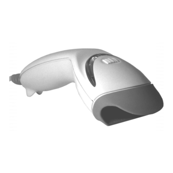
Page 14: Scanner Parts
CANNER ARTS Green & Red LEDs The MS5145’s laser pulses on and off when no bar code is presented, and stays on when it senses a bar code. The green LED remains on during normal pulse and scanning operation, and it blinks during power save mode. On a successful read of a bar code, the red LED will flash and the scanner will beep once. -
Page 15: The Ms5145 Eclipse™ Series
MS5145 E ™ S CLIPSE ERIES OW TO ATE AND THE ANUAL CTIVATION ® ANUAL CTIVATION This feature is not a default setting. Refer to the MetroSelect Configuration Guide for instructions on enabling the Manual Activation Mode. Figure 10a. Figure 10b. ODES OF PERATION CodeGate, Out-of-Stand... -
Page 16: Audible Indicators
UDIBLE NDICATORS When the MS5145 scanner is operational, it provides audible feedback. These sounds indicate the status of the scanner. Eight settings are available for the tone of the beep (normal, 6 alternate tones and no tone). To change the tone, refer to the Configuration Guide. -
Page 17: Visual Indicators
ISUAL NDICATORS There is a red LED and a green LED on the MS5145. When the scanner is on, the activity of the LEDs indicates the status of the current scan and the scanner. Green and Red LEDs are off The LEDs will not be illuminated if the scanner is not receiving power from the host or transformer. -
Page 18: Failure Modes
ODES One Razzberry Tone on Power-up This indicates the scanner has experienced a laser or flipper subsystem failure. Return the unit for repair to a Metrologic Authorized Service Center. Continuous Razzberry Tone with all LEDs off If, upon power up, the scanner emits a continuous razzberry tone, then the scanner has an experienced an electronic failure. -
Page 19: Programming Modes
MetroSet This user-friendly Windows-based configuration program allows you to simply ‘point-and-click’ at the desired scanner options. This program can be downloaded for FREE from Metrologic’ website (www.metrologic.com), or set-up disks can be ordered by calling 1-800-ID-METRO. Serial Programming This mode of programming is ideal for OEM applications. This mode gives the end-user the ability to send a series of commands using the serial port of the host system. - Page 20 ROGRAMMING ODES During programming, the motor and laser turn off. YOU CANNOT SCAN A BAR CODE WHILE IN SERIAL PROGRAM MODE. There is a 20 second window between commands. If a 20 second timeout occurs, the scanner will send a [nak] and you must start over. To enter serial program mode, send the following command [stx]999999[etx].
- Page 21 Programming Modes EXAMPLE #3: The following example shows the events that occur when an invalid bar code is sent. This sample will load the factory default settings and then set the baud rate to 19200. HOST SCANNER FEATURE COMMAND ASCII REPRESENTATION RESPONSE Enter Program Mode [stx]999999[etx]...
-
Page 22: Upgrading The Flash Rom Firmware
The MetroSet2 program is a functional component of Metrologic’s new line of Flash- based scanners. This program allows the user of a Metrologic scanner to quickly upgrade to a new or custom version of software. It requires the use of a personal computer running under Windows 95 or greater and the use of a communication port. -
Page 23: Scan Area
Minimum Bar Code Element Width mils 10.4... -
Page 24: Labels
ABELS Each scanner has one label on the underside of the unit. This label has the model number, date of manufacture, serial number, laser and caution information. The following is an example of this label. -
Page 25: Applications And Protocols
Keyboard Wedge, Stand-Alone Keyboard The MS5145Keyboard Wedge Series (-47) is designed for keyboard emulation only. Many RS232 programmable functions available in other Metrologic scanners are also available as keyboard wedge functions. The following are the most important selectable options specific to... -
Page 26: Troubleshooting Guide
ROUBLESHOOTING UIDE The following guide is for reference purposes only. Contact a Metrologic representative at 1-800-ID-Metro or 1-800-436-3876 to preserve the limited warranty terms. Symptoms Possible Causes Solution All Interfaces Check the transformer, the outlet No power is being and power strip. Make sure the supplied to the unit. - Page 27 ROUBLESHOOTING UIDE Symptoms Possible Causes Solution The bar code being Verify that the bar code being scanned does not The unit powers scanned falls into the satisfy the up, but does not programmed criteria. programmed criteria scan and/or for character length beep.
- Page 28 ROUBLESHOOTING UIDE Symptoms Possible Causes Solution Make sure that the proper PC type The unit scans The unit’s AT, PS2 or XT is selected. Verify but the data is configuration is not the correct country code and data not correct. correct.
-
Page 29: Rs232 Demonstration Program
RS232 D EMONSTRATION ROGRAM If an RS232 scanner is not communicating with your IBM compatible PC, key in the following BASIC program to test that the communication port and scanner are working. This program is for demonstration purposes only. It is only intended to prove that cabling is correct, the COM port is working, and the scanner is working. -
Page 30: Design Specifications
Single scan line Minimum Bar Width 0.089 mm (3.5 mil) Autodiscriminates all standard bar codes; for others Decode Capability call Metrologic RS232, Keyboard Wedge, USB ,Light Pen Emulation, System Interfaces IBM 468X/469X, OCIA, Stand Alone Keyboard Print Contrast 35% minimum reflectance difference... - Page 31 ESIGN PECIFICATIONS LECTRICAL Input Voltage 5 VDC ± 0.25 V Power - Operating 675 mW Current - Operating 125 mA peak @ 5 VDC DC Transformers Class 2; 5.2 V @ 650 mA UL listed for US and Canada; UL 60950, C22.2 No. 60950 CDRH and IEC Laser Class 1 In accordance Laser Class...
-
Page 32: Default Settings
EFAULT ETTINGS Many functions of the scanner can be “configured” or enabled/disabled. The scanner is shipped from the factory configured to a set of default conditions. All default parameters of the scanner have an asterisk ( * ) marked in the default column. - Page 33 EFAULT ETTINGS Light Laser Parameter Default OCIA RS232 46xx Emulation Mod 43 Check on Code 39 MSI-Plessy 10/10 Check Digit MSI-Plessy Mod 10 Check Digit Paraf Support ITF ITF Symbol Lengths Variable Minimum Symbol Length Symbol Length Lock None Bars High as Code 39 Spaces High as Code 39 Bars High as Scanned Spaces High as Scanned...
- Page 34 EFAULT ETTINGS Light Laser Parameter Default OCIA RS232 46xx Emulation Same symbol rescan timeout: 750 msecs Same symbol rescan timeout: 875 msecs Same symbol rescan timeout: 1000 msecs No Same symbol timeout Infinite Same symbol timeout Inter-character delay 1 msecs Program able in 1 msec steps 10 msecs (max 255 msecs)
- Page 35 EFAULT ETTINGS Light Laser Parameter Default OCIA RS232 46xx Emulation Transmit Sanyo ID Characters Nixdorf ID LRC Enabled UPC Prefix UPC Suffix Carriage Return Line Feed-Disabled by default in KBW Tab Prefix Tab Suffix “DE” Disable Command “FL” Laser Enable Command DTR Handshaking support RTS/CTS Handshaking Character...
- Page 36 EFAULT ETTINGS Light Laser Parameter Default OCIA RS232 46xx Emulation 100 msec to Find Supplement Programmable in 100 msec steps (max 800 msec) Coupon Code 128 code code 39 † Programmable Code 7 avail Lengths † Code Selects with programmable Code 3 avail Length Locks Programmable Prefix...
-
Page 37: Scanner And Cable Terminations
CANNER AND ABLE ERMINATIONS Scanner Pinout Connections MS5145-41 RS232C and Light Pen Emulation The MS5145scanner Function Interfaces terminate to a 10- pin modular jack. The serial # Ground label indicates the interface RS232 Transmit Output enabled when the scanner is RS232 Receive Input shipped from the factory. - Page 38 CANNER AND ABLE ERMINATIONS MS5145-9 OCIA Function Ground RS232 Transmit Output RS232 Receive Input RDATA RDATA Return Clock In Clock Out Clock in Return/Clock out Rtrn +5VDC Shield Ground MS5145-00 Laser Emulation Function Ground RS232 Transmit Output RS232 Receive Input Flip Sense/Start of Scan Output Proximity Detect/Trigger...
-
Page 39: Cable Connector Configurations
CANNER AND ABLE ERMINATIONS Cable Connector Configurations (Host End) “Standard” PowerLink Cable 55-55000A-3 Function Shield Ground RS232 Transmit Output RS232 Receive Input DTR Input/Light Pen Source Power/Signal Ground Light Pen Data (DSR Out for -14 interfaces) 9-Pin D-Type Connector CTS Input RTS Output +5VDC Stand Alone Keyboard PowerLink... - Page 40 PC Clock No Connect Metrologic will supply an adapter cable with a 5-pin DIN male connector on one end and a 6-pin mini DIN female connector on the other. According to the termination required, connect the appropriate end of the adapter cable to the PowerLink cable, leaving the necessary termination exposed for connecting to the keyboard and the keyboard port on the PC.
-
Page 41: Limited Warranty
In the event that it is determined the equipment failure is covered under this warranty, Metrologic shall, at its sole option, repair the Product or replace the Product with a functionally equivalent unit and return such repaired or replaced Product without charge for service or return freight, whether distributor, dealer/reseller, or retail consumer, or refund an amount equal to the original purchase price. -
Page 42: Laser And Product Safety
ASER AND RODUCT AFETY Notice This equipment has been tested and found to comply with the limits for a Class B digital device, pursuant to Part 15 of the FCC rules. These limits are designed to provide reasonable protection against harmful interference in a residential installation. - Page 43 ASER AND RODUCT AFETY Caution Caution Use of controls or adjustments or performance of procedures other than those specified herein may result in hazardous laser light exposure. Under no circumstances should the customer attempt to service the laser scanner. Never attempt to look at the laser beam, even if the scanner appears to be nonfunctional.
-
Page 44: Patents
ATENTS Patent Information “This METROLOGIC product may be covered by one or more of the following U.S. Patents: U.S. Patent No.; 5,260,553; 5,340,971; 5,424,525; 5,484,992; 5,525,789; 5,528,024; 5,616,908; 5,627,359; 5,661,292; 5,777,315; 5,789,730; 5,789,731; 5,811,780; 5,828,048; 5,925,870; 6,029,894; 6,209,789; 6,227,450; 6,283,375;... -
Page 45: Index
NDEX AC Input/Outlet......5, 6, 7 Host ..1, 2, 8, 13, 15, 17, 22–23 Accessories ........2 Adapter..........2 Audible ........12, 14 Indicators ......12, 13 LED ....... 4, 22–23 Installation........38 Bar code ........12, 13 Interfaces ....22, 26, 33, 35 Beep .. - Page 46 NDEX PowerLink....4, 5, 6, 7, 36 Troubleshooting ....22–23 Programming..4, 15, 16, 21, 24 Razzberry tone ..12, 13, 14, 29 Cable ......... 3 Red LED..4, 12, 13, 18, 22–23 Full Speed ......... 1 Repair..........14 Full Speed POS......8 RS232 ....
- Page 48 December 2004 Printed in China 7 0 - 7 9 0 1 6 B...