Table of Contents
Advertisement
Quick Links
SIMATIC NET
Industrial Ethernet Switches
SCALANCE X-200
Operating Instructions
11/2021
C79000-G8976-C284-15
Introduction
Safety notices
Recommendations on
network security
Description of the device
Installation and removal
Connecting up
Maintenance and cleaning
Technical specifications
Approvals
Dimension drawings
Test of mechanical stability
1
2
3
4
5
6
7
8
A
B
Advertisement
Table of Contents

Related Manuals for Siemens SIMATIC NET SCALANCE X-200


Summary of Contents for Siemens SIMATIC NET SCALANCE X-200
- Page 1 Introduction Safety notices Recommendations on network security SIMATIC NET Description of the device Industrial Ethernet Switches SCALANCE X-200 Installation and removal Connecting up Operating Instructions Maintenance and cleaning Technical specifications Approvals Dimension drawings Test of mechanical stability 11/2021 C79000-G8976-C284-15...
- Page 2 Note the following: WARNING Siemens products may only be used for the applications described in the catalog and in the relevant technical documentation. If products and components from other manufacturers are used, these must be recommended or approved by Siemens. Proper transport, storage, installation, assembly, commissioning, operation and maintenance are required to ensure that the products operate safely and without any problems.
-
Page 3: Introduction
Introduction Purpose of the Operating Instructions These operating instructions support you when commissioning networks with the devices of the product line SCALANCE X‑200. Validity of the Operating Instructions These Operating Instructions apply to the following devices: SCALANCE X-200 and SCALANCE XF-200 Device Article number X204‑2... - Page 4 You will find the Configuration Manual here: • On the data medium that ships with some products: – Product CD / product DVD – SIMATIC NET Manual Collection • On the Internet pages of Siemens Industry Online Support (https:// support.industry.siemens.com/cs/ww/en/ps/15247). SCALANCE X-200...
- Page 5 (https:// support.industry.siemens.com/cs/ww/en/ps/15247). SIMATIC NET glossary The SIMATIC NET glossary describes terms that may be used in this document. You will find the SIMATIC NET glossary in the Siemens Industry Online Support at the following address: 50305045 (https://support.industry.siemens.com/cs/ww/en/view/50305045) Security information Siemens provides products and solutions with industrial security functions that support the secure operation of plants, systems, machines and networks.
- Page 6 (https://www.siemens.com/industrialsecurity) Catalogs You will find the article numbers for the Siemens products of relevance here in the following catalogs: • SIMATIC NET Industrial Communication / Industrial Identification, catalog IK PI • SIMATIC Products for Totally Integrated Automation and Micro Automation, catalog ST 70 •...
- Page 7 Introduction Note the different national regulations. Trademarks The following and possibly other names not identified by the registered trademark sign ® registered trademarks of Siemens AG: SCALANCE, C-PLUG, OLM Electrostatic discharge NOTICE Electrostatic sensitive devices (ESD) Electronic modules contain electrostatic sensitive components These components can easily be destroyed if handled incorrectly.
- Page 8 Introduction SCALANCE X-200 Operating Instructions, 11/2021, C79000-G8976-C284-15...
-
Page 9: Table Of Contents
Table of contents Introduction ............................3 Safety notices ............................11 Recommendations on network security ....................13 Description of the device ........................19 Functions........................... 19 Product overview ....................... 22 Device views ........................24 Accessories ........................26 The LEDs..........................31 3.5.1 LED display when the device starts up ................31 3.5.2 Power LED "L"... - Page 10 Table of contents 5.3.1 Supply with X-200 via the terminal block................63 5.3.2 Supply for X208PRO......................64 5.3.3 Supply for IRT-PRO devices ....................64 5.3.4 Supply with XF-200IRT devices with bus adapter slots............66 Grounding ......................... 68 Signaling contact ....................... 69 Attachment to Industrial Ethernet ..................
-
Page 11: Safety Notices
Safety notices Read the safety notices Note the following safety notices. These relate to the entire working life of the device. You should also read the safety notices relating to handling in the individual sections, particularly in the sections "Installation" and "Connecting up". CAUTION To prevent injury, read the manual before use. - Page 12 Safety notices SCALANCE X-200 Operating Instructions, 11/2021, C79000-G8976-C284-15...
-
Page 13: Recommendations On Network Security
OpenVPN). • Separate connections correctly (WBM, Telnet, SSH etc.). • Check the user documentation of other Siemens products that are used together with the device for additional security recommendations. • Using remote logging, ensure that the system protocols are forwarded to a central logging server. - Page 14 Industrial Security (http://www.siemens.com/ industrialsecurity) website. • Inform yourself regularly about security recommendations published by Siemens ProductCERT (http://www.siemens.com/cert/en/cert-security-advisories.htm). • Only activate protocols that you require to use the device. • Disable encryption methods with a low security level.
- Page 15 Recommendations on network security Certificates and keys • As of firmware version V5.2.5, we converted from RSA certificates to certificates for elliptic curves cryptography ("ECDSA certificates"). Only use ECDSA certificates in PEM format that were generated with the following curves: –...
- Page 16 Recommendations on network security Secure/non-secure protocols • Avoid or disable non-secure protocols, for example Telnet and TFTP. For historical reasons, these protocols are available, however not intended for secure applications. Use non-secure protocols on the device with caution. • Check whether use of the following protocols and services is necessary: –...
- Page 17 Recommendations on network security • Factory setting Indicates the state of the port on delivery or after reset to factory settings. • Authentication Specifies whether the communication partner is authenticated. • Encryption Specifies whether or not the transfer is encrypted. Protocol Port number Port status...
- Page 18 Recommendations on network security SCALANCE X-200 Operating Instructions, 11/2021, C79000-G8976-C284-15...
-
Page 19: Description Of The Device
Description of the device Functions Functions of the X-200 IE Switches The X-200 IE switches are ideally suited for setting up Industrial Ethernet networks in bus, star and ring structures with transmission rates of 10/100 Mbps. All X-200 switches operate in the SIMATIC environment. - Page 20 Description of the device 3.1 Functions Special features of the X-200IRT IE switches The IRT variants were designed specifically for setting up Industrial Ethernet networks with isochronous/clock synchronous real-time communication. In addition to the properties named above, the IRT switches also provide the following functions: •...
- Page 21 Description of the device 3.1 Functions Overview of the functions The following table shows the hardware and software properties for each product variant of the X-200 switches in detail: Hardware Software Device type X204-2 ● ● ● ● ● ● ●...
-
Page 22: Product Overview
1. Make sure that the package is complete. 2. Check all the parts for transport damage. If the consignment is incomplete or damaged, contact your supplier or your local Siemens office. Components of the product The following parts ship with a SCALANCE X-200 IE switch: •... - Page 23 Description of the device 3.2 Product overview • Two 2-pin plug-in terminal blocks (power supply) • One DVD (configuration manual, operating instructions, SINEC PNI, SNMP OPC profiles) • In addition with the premounted variant SCALANCE XF202-2P IRT: – 2 bus adapters BA SCRJ/RJ-45 •...
-
Page 24: Device Views
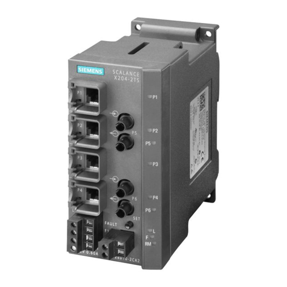
Description of the device 3.3 Device views Device views Device view based on the example of an X204-2TS The following figure describes the individual components of an IE switch X200. 1 LEDs for attachments to Industrial Ethernet 2 LEDs • L: Power LED, power supply •... - Page 25 Description of the device 3.3 Device views Device view based on the example of an XF204 The following figure describes the individual components of an IE switch X-200, flat design. LEDs • L: Power LED, power supply • F: Fault LED •...
-
Page 26: Accessories
Description of the device 3.4 Accessories Accessories C-PLUG Component Description Article number C-PLUG Configuration plug, exchangeable storage medium 6GK1 900-0AB00 for saving configuration data, 32 MB Configuration plug, exchangeable storage medium 6GK1 900-0AQ00 for saving configuration data, 32 MB, coated (con‐ formal coating) Configuration plug, exchangeable storage medium 6GK1 900-0AB10... - Page 27 Description of the device 3.4 Accessories Component Description Article number IE FC RJ-45 PLUG 180 RJ-45 data plug-in connector for IE FC cables 2x2, 6GK1 901-1BB10-2AB0 180° cable outlet, 10/100 Mbps, rugged metal housing 10 connectors per package IE FC RJ-45 PLUG 180 RJ-45 data plug-in connector for IE FC cables 2x2, 6GK1 901-1BB10-2AE0 180°...
- Page 28 Description of the device 3.4 Accessories Component Description Article number BA SCRJ/FC Media converter, PROFINET BusAdapter with 6ES7193-6AP40-0AA0 1 fiber-optic connector POF/PCF, SCRJ con‐ nection system and 1 FastConnect Ethernet connector for direct connection of the bus cable BA 2xLC PROFINET BusAdapter with 2 glass fiber-optic 6ES7193-6AG00-0AA0 connectors, LC connection system...
- Page 29 Description of the device 3.4 Accessories Note Note approvals of the bus adapters Bus adapters do not always have the same approvals as the basic devices. If you operate a basic device with a bus adapter that does not meet the conditions of an approval, this approval no longer applies to the basic device.
- Page 30 Description of the device 3.4 Accessories Strain relief Component Description Article number Strain relief Screw-on strain relief for guiding the outgo‐ 6ES7 193-6RA00-1AN0 ing cables The strain relief is a mechanical protective device for the electrical and optical cables on the bus adapter.
-
Page 31: The Leds
Description of the device 3.5 The LEDs The LEDs 3.5.1 LED display when the device starts up When the X-200 starts up, the LEDs light up in the following sequence: • The green power LED lights up immediately after turning on the device. •... -
Page 32: Redundancy Manager Led "Rm" (Green Led)
Description of the device 3.5 The LEDs The meanings of the fault LED display are as follows: LED color LED status Meaning Yellow The LED can only adopt this status with FM devices. Check the received power or the loss of power on optical connections. If necessary, replace the parts. -
Page 33: Standby Led "Rm" (Yellow Led)
Description of the device 3.5 The LEDs 3.5.5 Standby LED "RM" (yellow LED) You will find the standby LED only on devices with the IRT function. Note This LED labeled on the device with "RM" has a dual function. The color of the display changes depending on the function: •... -
Page 34: Diagnostics Leds For Optical Connectors "F" (Yellow Led)
Description of the device 3.5 The LEDs 3.5.7 Diagnostics LEDs for optical connectors "F" (yellow LED) You will find the diagnostics LEDs only on the devices with the IRT function. With the SCALANCE XF204-2BA IRT you will only find the diagnostics LEDs on bus adapters with SCRJ ports. The status of the optical connectors is indicated by an additional yellow LED per connector. -
Page 35: The Set Button
Description of the device 3.6 The SET button The SET button Function of the SET button With the SET button, you can change various settings of the device. The changed settings remain after cycling power to the device. Different settings are made depending on how long you hold down the SET button, as described in the following table: Figure 3-1 Phases for changing settings using the SET button... -
Page 36: The C-Plug
Description of the device 3.7 The C-PLUG The C-PLUG Area of application The C‑PLUG is an exchangeable medium for storage of the configuration and project engineering data of the basic device. This means that the configuration data remains available if the basic device is replaced. - Page 37 Description of the device 3.7 The C-PLUG Note If you insert a C-PLUG in a compatible device, the system name of the original device is entered both in the system name as well as in the PROFINET IO device name of the compatible device. Using a previously written C-PLUG If you want to insert a C-PLUG that has already been used and written to into a new differently configured X-200 IE switch, you will first need to delete the existing data on the C-PLUG.
- Page 38 Description of the device 3.7 The C-PLUG Figure 3-2 C-PLUG and slot based on the example of an X-200 You will find information regarding the location of the C-PLUG slot for the various product groups in the "Device views (Page 24)". Follow the steps below to insert the C-PLUG: 1.
-
Page 39: Starting The Device For The First Time
Description of the device 3.8 Starting the device for the first time Starting the device for the first time Note When the device is started up for the first time, the power-up time is approximately 1 minute longer than for all other starts of the device. The reason for this delay is the calculation of the certificates required for encrypted communication. - Page 40 Description of the device 3.8 Starting the device for the first time SCALANCE X-200 Operating Instructions, 11/2021, C79000-G8976-C284-15...
-
Page 41: Installation And Removal
Installation and removal Safety notices for installation Safety notices When installing the device, keep to the notices listed below. WARNING When used in ships, a DIN rail does provide adequate support For the following devices, installation on a 35 mm DIN rail for use in ships is not permitted: •... - Page 42 Installation and removal 4.1 Safety notices for installation WARNING Cable If the cable or conduit entry point exceeds 70 °C or the branching point of conductors exceeds 80 °C, special precautions must be taken. If the equipment is operated in an air ambient in excess of 50 °C, only use cables with admitted maximum operating temperature of at least 80 °C.
- Page 43 Installation and removal 4.1 Safety notices for installation Notes for use in hazardous locations according to ATEX, IECEx, UKEX and CCC Ex If you use the device under ATEX, IECEx, UKEX or CCC Ex conditions you must also keep to the following safety instructions in addition to the general safety instructions for protection against explosion: WARNING...
- Page 44 Installation and removal 4.1 Safety notices for installation Safety notices when using the device according to Hazardous Locations (HazLoc) If you use the device under HazLoc conditions you must also keep to the following safety notices in addition to the general safety notices for protection against explosion: WARNING Substitution of components may impair suitability for Class 1, Division 2.
- Page 45 Installation and removal 4.1 Safety notices for installation Further notes NOTICE Warming and premature aging of the IE switch due to direct sunlight Direct sunlight can heat up the device and can lead to premature aging of the IE switch and its cabling.
-
Page 46: Installation Options
Installation and removal 4.2 Installation options Installation options Types of installation IE Switches X‑200 can be installed in the following ways: • Installation on a 35 mm DIN rail complying with DIN EN 60715 • Installation on a SIMATIC S7-300 standard rail •... -
Page 47: Installation On A Din Rail
Installation and removal 4.3 Installation on a DIN rail Installation on a DIN rail Installation Figure 4-1 Installation on a 35 mm DIN rail To install an X-200 on a 35 mm DIN rail complying with DIN EN 60715, follow the steps below: 1. -
Page 48: Mounting Onto Standard Rail (Scalance Xf204-2Ba Irt)
Installation and removal 4.4 Mounting onto standard rail (SCALANCE XF204-2BA IRT) Mounting onto standard rail (SCALANCE XF204-2BA IRT) Installation Figure 4-2 DIN rail mounting To install the device on a 35 mm DIN rail complying with DIN EN 60715, follow the steps below: ①... - Page 49 Installation and removal 4.4 Mounting onto standard rail (SCALANCE XF204-2BA IRT) To remove the device from a DIN rail, follow the steps below: 1. Disconnect all connected cables. ① 2. Release the DIN rail locking mechanism by pressing down on the release button ②...
-
Page 50: Installation On A Standard Rail
Installation and removal 4.5 Installation on a standard rail Installation on a standard rail Installation on a SIMATIC S7-300 standard rail To install an X-200 on a standard rail, follow the steps below: 1. Fit the housing guide on the top of the housing into the standard rail. 2. -
Page 51: Wall Mounting
Installation and removal 4.6 Wall mounting Wall mounting Wall mounting Note The wall mounting must be capable of supporting at least four times the weight of the X-200, see section Technical specifications (Page 81). When mounting on a wall, use mounting fittings suitable for the type of wall. To secure the device in concrete, you could, for example use the following material: •... -
Page 52: Mounting Bus Adapters
Installation and removal 4.7 Mounting bus adapters Mounting bus adapters NOTICE Cover unused bus adapter slots If you do not cover unused bus adapter slots, this can lead to the following problems: • Loss of the approvals • Violation of the EMC regulations •... - Page 53 Installation and removal 4.7 Mounting bus adapters 5. Screw the bus adapter to the BaseUnit of the device with the supplied screw (tightening ② torque 0.2 Nm) Use the specified tool for this. 6. Insert the connection plugs into the sockets intended for this on the bus adapter. Removal To remove a bus adapter, follow the steps below: 1.
-
Page 54: Mounting Tensile Strain Relief
Installation and removal 4.8 Mounting tensile strain relief Mounting tensile strain relief Required tools • Torx screwdriver, size T10 • Cable ties We recommend cable ties with a width of 4.8 mm. The maximum width is 7.0 mm. The length of the cable tie is min. 60 mm. Installation Figure 4-6 Mounting tensile strain relief... -
Page 55: Disassembly
Installation and removal 4.9 Disassembly Disassembly WARNING Improper disassembly Improper disassembly may result in a risk of explosion in hazardous areas. For proper disassembly, observe the following: • Before starting work, ensure that the electricity is switched off. • Secure remaining connections so that no damage can occur as a result of disassembly if the system is accidentally started up. - Page 56 Installation and removal 4.9 Disassembly SCALANCE X-200 Operating Instructions, 11/2021, C79000-G8976-C284-15...
-
Page 57: Connecting Up
Connecting up Safety when connecting up Safety notices When connecting up the device, keep to the safety notices listed below. WARNING Power supply The device is designed for operation with a directly connectable safety extra low voltage (SELV) from a limited power source (LPS). The power supply therefore needs to meet at least one of the following conditions: •... - Page 58 Connecting up 5.1 Safety when connecting up Note Safety extra-low voltage The supply of the devices by PELV (Protective Extra Low Voltage) according to DIN VDE 0100-410 or IEC 60364-4-41 is permitted when the generated nominal voltage does not exceed the voltage limits 25 VAC or 60 VDC.
- Page 59 Connecting up 5.1 Safety when connecting up WARNING Unsuitable cables or connectors Risk of explosion in hazardous areas • Only use connectors that meet the requirements of the relevant type of protection. • If necessary, tighten the connector screw connections, device fastening screws, grounding screws, etc.
- Page 60 Connecting up 5.1 Safety when connecting up Notes for use in hazardous locations according to ATEX, IECEx, UKEX and CCC Ex If you use the device under ATEX, IECEx, UKEX or CCC Ex conditions you must also keep to the following safety instructions in addition to the general safety instructions for protection against explosion: WARNING...
- Page 61 Connecting up 5.1 Safety when connecting up NOTICE Overvoltage protection If IE Switches X‑200 are supplied over long 24 V power supply lines or networks, measures are necessary to prevent interference by strong electromagnetic pulses on the supply lines. These can result, for example, due to lightning or switching of large inductive loads.
-
Page 62: Wiring Rules
Connecting up 5.2 Wiring rules Wiring rules When wiring use cables with the following AWG categories or cross sections. Wiring rules for ... Screw/spring-loaded ter‐ minals connectable cable cross sec‐ without wire end ferrule 0.25 - 2.5 mm tions for flexible cables ... AWG: 24 - 13 with wire end ferrule with plastic fer‐... -
Page 63: Power Supply
Connecting up 5.3 Power supply Power supply 5.3.1 Supply with X-200 via the terminal block Power supply The power supply is connected via a 4-pin plug-in terminal block that ships with the device. • The power supply can be connected redundantly. –... -
Page 64: Supply For X208Pro
Connecting up 5.3 Power supply 5.3.2 Supply for X208PRO Power supply for X208PRO With the IE switch SCALANCE X208PRO, the power supply is connected via two 4-pin a-coded M12 sockets. • The power supply can be connected redundantly. – Both inputs are isolated. –... - Page 65 In areas subject to the EU directives ATEX and IECEX of the National Electric Code (NEC), the Canadian Electric Code (CEC) and UL, metal connectors must be used. Further information and technical advice on this subject is available from: Jürgen Hertlein, juergen.hertlein@siemens.com. Power supply • Power: 24 VDC •...
-
Page 66: Supply With Xf-200Irt Devices With Bus Adapter Slots
5.3 Power supply You should also refer to the manual "SIMATIC Distributed IO System ET 200pro (https:// support.industry.siemens.com/cs/ww/en/view/21210852)". Note Notes on operating under marginal conditions When looping through the power supply, take into account the limit values; in other words, the maximum permitted current depending on the ambient temperature;... - Page 67 Connecting up 5.3 Power supply Information on the power supply • The power supply is connected via two 2-pin plug-in terminal blocks that ship with the device. • The power supply can be connected redundantly. – Both inputs are isolated. –...
-
Page 68: Grounding
Connecting up 5.4 Grounding Grounding Grounding when installing on a DIN rail The device is grounded over the DIN rail. Grounding when installing on an S7 standard rail The device is grounded over its rear panel and the neck of the screw. Grounding with wall mounting The device is grounded by the securing screw in the unpainted hole. -
Page 69: Signaling Contact
Connecting up 5.5 Signaling contact Signaling contact Signaling contact The signaling contact or relay contact is a floating switch with which error/fault states can be signaled by breaking the contact. The following errors/faults can be signaled by the signaling contact: •... - Page 70 Connecting up 5.5 Signaling contact The following table shows the pin assignment: Assignment no.: n.c. n.c. n.c. SCALANCE X-200 IRT PRO SCALANCE X-200 Operating Instructions, 11/2021, C79000-G8976-C284-15...
-
Page 71: Attachment To Industrial Ethernet
Connecting up 5.6 Attachment to Industrial Ethernet Attachment to Industrial Ethernet Note Redundancy mechanisms If you use redundancy mechanisms such as media redundancy "HRP" or "MRP" and/or redundant linking of rings via a standby link, remember the following: Open the redundant path before you insert a new device or replacement device in an operating network. - Page 72 Connecting up 5.6 Attachment to Industrial Ethernet MDI / MDI-X autocrossover function The advantage of this function is that straight-through cables can be used throughout and external Ethernet crossover cables are unnecessary. This prevents malfunctions resulting from mismatching send and receive wires. This makes installation much easier for the user. Note Formation of loops Please note that the direct connection of two ports on the switch or accidental connection over...
-
Page 73: Electrical Connectors Of The X208Pro
Connecting up 5.6 Attachment to Industrial Ethernet Pin assignment The following table shows the pin assignment of the RJ-45 connectors: Pin no.: Assignment n. c. n. c. n. c. n. c. Permitted cable lengths • With connection using TP cords or TP-XP cords: maximum 10 m •... -
Page 74: Optical Attachments To Industrial Ethernet
Connecting up 5.6 Attachment to Industrial Ethernet Pin assignment The following table shows the pin assignment of the M12 sockets: Pin no.: Assignment Permitted cable lengths • With connection using TP cords or TP-XP cords: maximum 10 m • When connected using IE FC cable with IE RJ45 plug: Depending on the cable type, a total length of up to 100 m is permitted between two devices. -
Page 75: Multimode Fiber-Optic Cable
Connecting up 5.6 Attachment to Industrial Ethernet 5.6.2.1 Multimode fiber-optic cable Transmission medium The following X-200 IE switches use multimode fiber-optic cables as the transmission medium: • X204-2 • X204-2TS • X204-2FM • X206-1 • X212-2 • XF204-2 • XF206-1 •... -
Page 76: Single Mode Fiber-Optic Cable
Connecting up 5.6 Attachment to Industrial Ethernet 5.6.2.2 Single mode fiber-optic cable Transmission medium The following X-200 IE switches use single mode fiber-optic cables as the transmission medium: • X204-2LD • X204-2LD TS • X206-1LD • X212-2LD Characteristics: Transmission speed 100 Mbps Transmission mode 100Base LX... -
Page 77: Push-Pull Connector For Irt-Pro Devices
Connecting up 5.6 Attachment to Industrial Ethernet Characteristics: Transmission speed 100 Mbps Transmission mode 100Base-FX analogous to IEEE 802.3 Connectors SC RJ jacks Wavelength 650 nm Core diameter • with POF • 980 μm • with PCF • 200 μm Outer diameter •... - Page 78 Connecting up 5.6 Attachment to Industrial Ethernet Due to their high degree of protection (IP65), the push-pull connectors are suitable for installation outside cabinets. The plugs do not ship with the product, see the section “Accessories (Page 26)“. SCALANCE X-200 Operating Instructions, 11/2021, C79000-G8976-C284-15...
-
Page 79: Maintenance And Cleaning
Maintenance and cleaning WARNING Unauthorized repair of devices in explosion-proof design Risk of explosion in hazardous areas • Repair work may only be performed by personnel authorized by Siemens. WARNING Impermissible accessories and spare parts Risk of explosion in hazardous areas •... - Page 80 Maintenance and cleaning SCALANCE X-200 Operating Instructions, 11/2021, C79000-G8976-C284-15...
-
Page 81: Technical Specifications
Technical specifications Construction Type Dimensions (W x H x D) in mm Weight in g Installation options - DIN rail - S7-300 standard rail - Wall mounting X204-2 60 x 125 x 124 X204-2TS 60 x 125 x 124 X204-2FM 60 x 125 x 124 X204-2LD 60 x 125 x 124... - Page 82 Technical specifications Ports Type Connectors for end devi‐ Connections for end devi‐ Connectors for power Connectors for ces or network compo‐ ces or network compo‐ supply signaling contact nents via twisted pair nents via FO cable 4-pin plug-in terminal 2-pin plug-in terminal RJ-45 jacks with MDI X BFOC sockets block, redundant...
- Page 83 Technical specifications Type Connectors for end devi‐ Connections for end devi‐ Connector for power sup‐ Connector for signaling ces or network compo‐ ces or network compo‐ contact nents via twisted pair nents via FO cable 5-pin Power Plug PRO 5-pin b-coded M12 con‐ RJ-45 jacks with MDI X SC RJ jacks (push-pull), connector (male)
- Page 84 Technical specifications Type Supply voltage with re‐ Power loss at 24 VDC Current consumption at Overcurrent protection dundant connection rated voltage at input PTC resettable fuse Rated voltage 24 VDC Voltage range 19.2 VDC to 28.8 VDC Permitted voltage range incl.
- Page 85 Technical specifications Optical data Type Transmitter output (optical) Receiver input min. [dBm] max. [dBm] Sensitivity min. [dBm] Input power max. [dBm] X204-2 X204-2TS X204-2FM X206-1 X212-2 XF204-2 XF206-1 X202-2IRT X204-2LD X204-2LD TS X206-1LD X212-2LD X200-4P IRT X201-3P IRT X201-3P IRT PRO X202-2P IRT X202-2P IRT PRO Type...
- Page 86 Technical specifications For devices with the "PRO" supplement (degree of protection IP65) With these devices, splitting of the cables (as above) is not permitted. The following cables are permitted in the specified lengths: • 0 to 55 m: IE TP torsion cable with IE FC RJ-45 Plug 180 •...
- Page 87 Technical specifications Type 1 ‑ 50 m 1 ‑ 100 m 0 ‑ 4000 0 - 26000 m 980/1000 plastic optical 200/230 polymer cladded Glass FO cable glass FO cable fiber (POF) fiber (PCF) 62.5/125 µm glass fibers 9/125 µm single mode fi‐ 6 dB max.
- Page 88 Technical specifications Switching properties Type Max. number of learn‐ Aging time Switching technique Latency able addresses X-200 8000 30 s Store and forward 5 μs XF-200 8000 30 s Store and forward 5 μs X-200IRT 4096 30 s (configurable) Store and forward / cut through <...
- Page 89 Technical specifications Permitted ambient conditions Note Note the mounting position for XF and TS devices With the following switches an ambient temperature of maximum +40 °C is permitted if the device is installed on a vertical rail: • XF204 • XF208 •...
- Page 90 Technical specifications Type Operating temperature Storage/transport tem‐ Rel. humidity in op‐ Operating altitude at max. xx perature eration (no conden‐ °C ambient temperature sation) XF208 -40 °C to +60 ℃ *) -40 °C to +70 ℃ ‹ 95 % 2000 m at max. 56 ℃ 3000 m at max.
- Page 91 Technical specifications Frame delay times The number of IE Switches X-200 connected in a line influences the frame delay. Note Frame delay time with X‑200 without IRT When a frame passes through X-200 IE switches, it is delayed by the Store&Forward function of the X-200 IE switches.
- Page 92 Technical specifications SCALANCE X-200 Operating Instructions, 11/2021, C79000-G8976-C284-15...
-
Page 93: Approvals
Approvals for shipbuilding are not printed on the device type plate. Current approvals on the Internet You will find the current approvals for the product on the Internet pages of Siemens Industry Online Support (https://support.industry.siemens.com/cs/ww/en/ps/15273/cert). Notes for the manufacturers of machines The devices are not machines in the sense of the EC Machinery Directive. - Page 94 Process Automation DE-76181 Karlsruhe Germany Importer UK: Siemens plc, Manchester M20 2UR You can find the current UK Declaration of Conformity for these products on the Internet pages under Siemens Industry Online Support (https://support.industry.siemens.com/cs/ww/en/ps/ 15273/cert). SCALANCE X-200 Operating Instructions, 11/2021, C79000-G8976-C284-15...
- Page 95 "SIMATIC NET Product Information Use of subassemblies/modules in a Zone 2 Hazardous Area". You will find this document • on the data medium that ships with some devices. • on the Internet pages under Siemens Industry Online Support (https:// support.industry.siemens.com/cs/ww/en/view/78381013).
- Page 96 Approvals You will find the current versions of the standards in the currently valid certificates. Note for devices with CLASS 1 LASER Important note on products certified according to Type Examination Certificate KEMA 07ATEX0145 X as of Issue 95 / DEKRA 18ATEX0025 X and IECEx Certificate of Conformity DEK 14.0025X as of Issue 43 / DEK 18.0017X and containing Class 1 optical radiation sources.
- Page 97 Approvals RoHS The SIMATIC NET products described in these operating instructions meet the requirements on the restriction of the use of certain hazardous substances in electrical and electronic equipment according to the EU Directive 2011/65/EU as well as the UK-Regulation SI 2012/3032 and their associated amendments.
- Page 98 Approvals Underwriters Laboratories Inc. according to either • UL 60950-1 (Information Technology Equipment) • CSA C22.2 No. 60950-1 (information technology equipment) • ANSI/ISA 12.12.01 • CSA C22.2 No. 213 • UL 62368-1 (information/communication technology) • CSA C22.2 No. 62368-1 (information/communication technology) •...
- Page 99 Approvals Shipbuilding Note that the approvals for shipbuilding with the SCALANCE XF204-2BA IRT are valid with all bus adapters, see section "Accessories (Page 26)". FDA and IEC marking The following devices meet the FDA and IEC requirements listed below: Device CLASS 1 LASER Product SCALANCE X200-4P IRT ●...
- Page 100 • "Industrial Ethernet / PROFINET Industrial Ethernet" System Manual (https:// support.industry.siemens.com/cs/ww/en/view/27069465) • "Industrial Ethernet / PROFINET - Passive Network Components" System Manual (https:// support.industry.siemens.com/cs/ww/en/view/84922825) • "EMC Installation Guidelines" configuration manual (https:// support.industry.siemens.com/cs/ww/en/view/60612658)
-
Page 101: Dimension Drawings
Dimension drawings Figure A-1 Drilling pattern SCALANCE X204‑2, X204-2TS, X204-2FM, X204‑2LD, X204‑2LD TS, X206‑1, X206‑1LD, X208, X200‑4P IRT, X201‑3P IRT, X202‑2IRT, X202‑2P IRT, X204IRT SCALANCE X-200 Operating Instructions, 11/2021, C79000-G8976-C284-15... - Page 102 Dimension drawings Figure A-2 Drilling pattern SCALANCE X212-2, X212-2LD and X216 SCALANCE X-200 Operating Instructions, 11/2021, C79000-G8976-C284-15...
- Page 103 Dimension drawings Figure A-3 Drilling pattern SCALANCE X224 Figure A-4 Side view SCALANCE X-200 SCALANCE X-200 Operating Instructions, 11/2021, C79000-G8976-C284-15...
- Page 104 Dimension drawings Figure A-5 Side view SCALANCE X-200 POF with POF interface Figure A-6 Dimension drawings of the SCALANCE X208PRO, SCALANCE X201-3P IRT PRO, SCALANCE X202-2P IRT PRO and SCALANCE X204IRT PRO SCALANCE X-200 Operating Instructions, 11/2021, C79000-G8976-C284-15...
- Page 105 Dimension drawings Figure A-7 Drilling pattern of the SCALANCE X208PRO, SCALANCE X201-3P IRT PRO, SCALANCE X202-2P IRT PRO and SCALANCE X204IRT PRO SCALANCE X-200 Operating Instructions, 11/2021, C79000-G8976-C284-15...
- Page 106 Dimension drawings Figure A-8 SCALANCE XF-200 dimension drawings Figure A-9 Dimension drawing SCALANCE XF204-2BA IRT SCALANCE X-200 Operating Instructions, 11/2021, C79000-G8976-C284-15...
-
Page 107: Test Of Mechanical Stability
Test of mechanical stability Mechanical stability Device type IEC 60068-2-6 vibration IEC 60068-2-27 shock SCALANCE X204-2 5 – 9 Hz: 3.5 mm 15 g, 6 ms duration 9 – 500 Hz: 1 g 6 shocks per axis 1 octave/min, 20 sweeps X204-2TS 5 –... - Page 108 Test of mechanical stability Device type IEC 60068-2-6 vibration IEC 60068-2-27 shock SCALANCE XF204-2 5 – 9 Hz: 3.5 mm 15 g, 6 ms duration 9 – 500 Hz: 1 g 6 shocks per axis 1 octave/min, 20 sweeps XF206-1 5 –...
-
Page 109: Index
Index Approvals, 93 MDI / MDI-X autocrossover, 72, 73 Article number, 3 C-PLUG, 26 Power Plug PRO, 64 Redundancy module, 26 Node localization, 34 RJ-45 data plug-in connector, 26 Number of connectors, 21 SC RJ plug-in connector, 27 Auto polarity exchange, 72 Autonegotiation, 72 Order number C-PLUG, 37... - Page 110 Index SCALANCE X-200 Operating Instructions, 11/2021, C79000-G8976-C284-15...