
Related Manuals for Siemens SIMATIC NET RUGGEDCOM RS910W


Summary of Contents for Siemens SIMATIC NET RUGGEDCOM RS910W
- Page 1 Installation Manual SIMATIC NET Rugged Ethernet Switches RUGGEDCOM RS910W Edition 04/2021 https://www.siemens.com...
- Page 2 Preface Introduction Installing the Device SIMATIC NET Device Management Rugged Ethernet Switches RUGGEDCOM RS910W Communication Ports Technical Specifications Installation Manual Certification 04/2021 C79000-G8976-1031-12...
- Page 3 Note the following: WARNING Siemens products may only be used for the applications described in the catalog and in the relevant technical documentation. If products and components from other manufacturers are used, these must be recommended or approved by Siemens. Proper transport, storage, installation, assembly, commissioning, operation and maintenance are required to ensure that the products operate safely and without any problems.
-
Page 4: Table Of Contents
Accessing Documentation ....................... v Registered Trademarks ......................v Warranty ..........................v Training ..........................vi Customer Support ........................vi Contacting Siemens ....................... vii Introduction ........................... 1 Feature Highlights ....................2 Description ......................2 Required Tools and Materials ................. 4 Decommissioning and Disposal ................4 Cabling Recommendations .................. - Page 5 Table of Contents 4.3.2 Radio Characteristics ................... 26 4.3.3 Channel Allocations for IEEE 802.11b/g ............... 27 Serial Ports ......................27 4.4.1 Serial RS232/RS485/RS422 DB9 Ports ..............28 4.4.2 Serial RS232/RS485/RS422 RJ45 Ports ..............28 4.4.3 Serial RS232/RS485/RS422 Fiber Ports ..............29 4.4.4 Connecting Multiple RS485 Devices ..............
-
Page 6: Preface
Warranty Siemens warrants this product for a period of five (5) years from the date of purchase, conditional upon the return to factory for maintenance during the warranty term. This product contains no user-serviceable parts. Attempted service by unauthorized personnel shall render all warranties null and void. -
Page 7: Training
Siemens Sales representative. Customer Support Customer support is available 24 hours, 7 days a week for all Siemens customers. For technical support or general information, contact Siemens Customer Support through any of the following methods: Online Visit http://www.siemens.com/automation/support-request... -
Page 8: Contacting Siemens
Preface Contacting Siemens • Contact a local Siemens representative from Sales, Technical Support, Training, etc. • Ask questions or share knowledge with fellow Siemens customers and the support community Contacting Siemens Address Siemens AG Industry Sector 300 Applewood Crescent Concord, Ontario... - Page 9 Preface Contacting Siemens viii RUGGEDCOM RS910W Installation Manual, 04/2021, C79000-G8976-1031-12...
-
Page 10: Introduction
Introduction The RUGGEDCOM RS910W is a utility-grade serial device server that combines an IEEE 802.11b/g Local Area Network (LAN) with wired serial and Ethernet ports. It allows network designers to connect any RS232/422/485 serial device at up to 230 kbps and/or connect Ethernet devices for wireless access and control via an IEEE 802.11i WLAN. -
Page 11: Feature Highlights
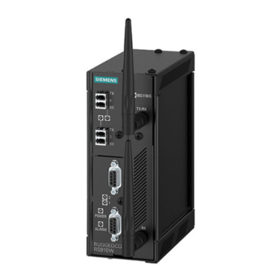
Introduction 1.1 Feature Highlights Feature Highlights Serial Device Server • 2 x fully compliant EIA/TIA RS485/RS422/RS232 serial ports (software selectable) • Baud rates up to 230 kbps • 2 x RS485/RS422/RS232 Serial Ports (DB9 or RJ45) • [Optional] Built-in RS485 termination Ethernet Ports •... - Page 12 Introduction 1.2 Description POWER LED ALARM LED [Optional] Copper (10/100Base-TX) or Fiber Optic (100Base-FX) Ethernet Ports Wireless Ethernet Ports Serial Ports RS232 Console Port (Serial) Failsafe Alarm Relay Chassis Ground Connection Power Supply Terminal Block Figure 1.1 RUGGEDCOM RS910W POWER LED Illuminates green during boot up and when power is supplied to the device.
-
Page 13: Required Tools And Materials
Siemens also does not recommend using copper Ethernet ports to interface with devices in the field across distances that could produce high levels of ground potential rise (i.e. greater than 2500 V), during line-to-ground fault conditions. -
Page 14: 1.5.1 Supported Fiber Optic Cables
Introduction 1.5.1 Supported Fiber Optic Cables 1.5.1 Supported Fiber Optic Cables The following fiber optic cable types are supported under the stated conditions. Cable Type Wavelength (nm) Modal Bandwidth Distance (m) (MHz·km) 100Base-FX 1000Base-SX 10GBase-SR OM1 (62.5/125) — 1300 2000 — —... - Page 15 Introduction 1.5.1 Supported Fiber Optic Cables RUGGEDCOM RS910W Installation Manual, 04/2021, C79000-G8976-1031-12...
-
Page 16: Installing The Device
This product contains no user-serviceable parts. Attempted service by unauthorized personnel shall render all warranties null and void. Changes or modifications not expressly approved by Siemens AG could invalidate specifications, test results, and agency approvals, and void the user's authority to operate the equipment. -
Page 17: General Procedure
Visually inspect each item in the package for any physical damage. Verify all items are included. Note If any item is missing or damaged, contact Siemens for assistance. Installing the Device in Hazardous Locations The RUGGEDCOM RS910W is designed to comply with the safety standards for Class I, Division 2 hazardous locations where concentrations of flammable gases, vapors or liquids may be present, as opposed to normal operating environments. -
Page 18: Mounting The Device
Installing the Device 2.4 Mounting the Device Note The device is certified for installation in hazardous environments as a component only. It is required to be installed in a suitable enclosure where the final combination is subject to acceptance by an authorized local inspection authority. Installation and use of the device in a hazardous location should meet the following special conditions for safe use: •... -
Page 19: 2.4.1 Mounting The Device On A Din Rail
Installing the Device 2.4.1 Mounting the Device on a DIN Rail Note For detailed dimensions of the device with either DIN rail or panel hardware installed, refer to "Dimension Drawings (Page 34)". 2.4.1 Mounting the Device on a DIN Rail The RUGGEDCOM RS910W can be ordered with a DIN rail adapter preinstalled on the back of the chassis. -
Page 20: Mounting The Device To A Panel
Installing the Device 2.4.2 Mounting the Device to a Panel Push the device against the bottom of the DIN rail, then let go of the sliding release to latch the device. Removing the Device To remove the device from a DIN rail, do the following: Insert a flathead screwdriver into the slot of the sliding release and move it down. -
Page 21: Connecting The Antennas
Installing the Device 2.5 Connecting the Antennas Place the device against the panel and align the adapters with the mounting holes. Screw (M3.5 or #6-32) Panel Mount Adapter Figure 2.3 Panel Mounting Secure the adapters to the panel with M3.5 or #6-32 screws. Connecting the Antennas The RUGGEDCOM RS910W supports two dipole antennas that can be rotated 360°... -
Page 22: Connecting The Failsafe Alarm Relay
Installing the Device 2.6 Connecting the Failsafe Alarm Relay Align the antenna connector with the wireless port (either TX/RX or RX) and thread the antenna onto the port. Make sure the connection is finger tight. Figure 2.4 Antenna Installation Repeat Step 2 for the second antenna. -
Page 23: Connecting Power
Installing the Device 2.7 Connecting Power Connect a failsafe device to the terminal block. Normally Closed Common Normally Open Figure 2.5 Failsafe Alarm Relay Wiring Connecting Power The RUGGEDCOM RS910W supports power input from a single high AC/DC or low DC power supply. Note •... -
Page 24: Connecting High Ac/Dc Power
Installing the Device 2.7.1 Connecting High AC/DC Power 2.7.1 Connecting High AC/DC Power To connect a high AC/DC power supply to the device, do the following: NOTICE Electrical hazard – risk of damage to equipment Do not connect AC power cables to terminals for DC power. Damage to the power supply may occur. - Page 25 Installing the Device 2.7.1 Connecting High AC/DC Power Connect the positive wire from the power source to the positive/live (+/L) terminal on the terminal block. Positive/Live (+/L) Terminal Negative/Neutral (-/N) Terminal Surge Ground Terminal Braided Ground Cable Figure 2.6 Terminal Block Wiring RUGGEDCOM RS910W Installation Manual, 04/2021, C79000-G8976-1031-12...
-
Page 26: 2.7.2 Connecting Low Dc Power
Installing the Device 2.7.2 Connecting Low DC Power ± ± ± ± Positive Terminal Negative Terminal Surge Ground Terminal Braided Ground Cable Figure 2.7 Terminal Block Wiring – Dual DC Power Supply Inputs Connect the negative wire from the power source to the negative/neutral (-/N) terminal on the terminal block. - Page 27 Installing the Device 2.7.2 Connecting Low DC Power Connect the positive wire from the power source to the positive terminal on the terminal block. ± ± Positive Terminal Negative Terminal Surge Ground Terminal Braided Ground Cable Figure 2.8 Terminal Block Wiring – Single DC Power Supply Inputs Connect the negative wire from the power source to the negative terminal on the terminal block.
- Page 28 Installing the Device 2.7.2 Connecting Low DC Power [Optional] If a redundant connection is required, repeat Step 2 Step 3 connect the secondary power inputs. ± ± ± ± Positive Terminal Negative Terminal Surge Ground Terminal Braided Ground Cable Figure 2.9 Terminal Block Wiring – Dual DC Power Supply Inputs Using a braided wire or other appropriate grounding wire, connect the surge ground terminal to the chassis ground connection.
- Page 29 Installing the Device 2.7.2 Connecting Low DC Power RUGGEDCOM RS910W Installation Manual, 04/2021, C79000-G8976-1031-12...
-
Page 30: Device Management
Device Management This section describes how to connect to and manage the device. Connecting to the Device The following describes the various methods for accessing the RUGGEDCOM RS910W console and Web interfaces on the device. For more detailed instructions, refer to the RUGGEDCOM ROS Configuration Manual for the RUGGEDCOM RS910W. -
Page 31: Configuring The Device
Device Management 3.2 Configuring the Device The serial console port implements RS232 DCE (Data Communication Equipment) on a DB9 connector. The following is the pin-out for the port: Name Description Reserved (Do Not Connect) Transmit Data Receive Data Reserved (Do Not Connect) Signal Ground Reserved (Do Not Connect) Reserved (Do Not Connect) -
Page 32: Communication Ports
Communication Ports The RUGGEDCOM RS910W can be equipped with various types of communication ports to enhance its abilities and performance. Ports 1 and 2 Ports 3 and 4 Port 9 Figure 4.1 Port Assignment Port Type 1 and 2 Serial Ports 3 and 4 Copper (10/100Base-TX) or Fiber Optic (100Base-FX) Ethernet Ports Wireless Antennas... - Page 33 Communication Ports 4.1 Copper Ethernet Ports WARNING Electric shock hazard – risk of serious personal injury and/or equipment interference When shielded cables are used, make sure the shielded cables do not form a ground loop via the shield wire and the RJ45 receptacles at either end. Ground loops can cause excessive noise and interference, but more importantly, create a potential shock hazard that can result in serious injury.
-
Page 34: Fiber Optic Ethernet Ports
Communication Ports 4.2 Fiber Optic Ethernet Ports Name Description Transmit Data- Reserved (Do Not Connect) Reserved (Do Not Connect) Specifications For specifications on the available copper Ethernet ports, refer to "Copper Ethernet Port Specifications (Page 32)". Fiber Optic Ethernet Ports Fiber optic Ethernet ports are available with either MTRJ (Mechanical Transfer Registered Jack), LC (Lucent Connector), SC (Standard or Subscriber Connector) or ST (Straight Tip) connectors. -
Page 35: Wireless Ethernet Ports
Communication Ports 4.3 Wireless Ethernet Ports State Description No link detected Specifications For specifications on the available fiber optic Ethernet ports, refer to "Fiber Optic Ethernet Port Specifications (Page 33)". Wireless Ethernet Ports The RUGGEDCOM RS910W supports an optional set of IEEE 802.11 compliant wireless Ethernet ports for accessing a Wireless Local Area Network (WLAN). -
Page 36: Channel Allocations For Ieee 802.11B/G
Communication Ports 4.3.3 Channel Allocations for IEEE 802.11b/g 63 mW (18 dBm) 802.11g 48 Mbps Data Rate 40 mW (16 dBm) 802.11g 54 Mbps Data Rate Receiver Sensitivity At Radio 802.11b 11 Mb @ -88 dBm/With Antenna: 11 Mb @ -91 dBm At Radio 802.11g 54 Mb @ -74 dBm/With Antenna: 54 Mb @ -77 dBm 4.3.3 Channel Allocations for IEEE 802.11b/g... -
Page 37: 4.4.1 Serial Rs232/Rs485/Rs422 Db9 Ports
Communication Ports 4.4.1 Serial RS232/RS485/RS422 DB9 Ports information, refer to the RUGGEDCOM ROS Configuration Manual for the RUGGEDCOM RS910W. All serial ports feature an LED that indicates the current state of the port. State Description Green Link activity detected No link detected For specifications on serial ports, refer to "Serial Port Specifications (Page 33)". -
Page 38: 4.4.3 Serial Rs232/Rs485/Rs422 Fiber Ports
Communication Ports 4.4.3 Serial RS232/RS485/RS422 Fiber Ports system to operate in RS232, RS485 or RS422 mode. For more information, refer to the RUGGEDCOM ROS Configuration Manual for the RUGGEDCOM RS910W. The following is the pin-out description for the RS232/RS485/RS422 RJ45 ports: ... - Page 39 Communication Ports 4.4.4 Connecting Multiple RS485 Devices the same two wires (half duplex). For reliable, continuous communication, adhere to the following guidelines: • To minimize the effects of ambient electrical noise, use shielded cabling. • The correct polarity must be observed throughout a single sequence or ring. •...
-
Page 40: Technical Specifications
Technical Specifications This section provides important technical specifications related to the device. Power Supply Specifications Note When determining cable lengths, make sure the minimum input voltage for the power supply is provided at the power source. Hazardous Environments Power Input Range Internal Isolation Maximum Power... -
Page 41: Failsafe Alarm Relay Specifications
Technical Specifications 5.2 Failsafe Alarm Relay Specifications Failsafe Alarm Relay Specifications Hazardous Environments Maximum Switching Voltage Rated Isolation Switching Current 30 VDC 1500 V for 1 minute 80 VDC 0.3 A 30 VAC Non-Hazardous Environment Maximum Switching Voltage Rated Isolation Switching Current 30 VDC 2 A, 60 W... -
Page 42: Fiber Optic Ethernet Port Specifications
3 dBm. To convert from peak to average, subtract 3 dBm. • Maximum segment length is greatly dependent on factors such as fiber quality, and the number of patches and splices. Consult a Siemens sales associate when determining maximum segment distances. Tx (dBm) -
Page 43: Operating Environment
Technical Specifications 5.7 Operating Environment Copper Serial Ports Baud Rate 300 to 230 kbps Connector DB9 or RJ45 Isolation 2.5 kV Fiber Serial Ports Mode Multimode Connector Typical Distance (km) Optical Wavelength (nm) Cable Size 50/125 or 62.5/125 Operating Environment The RUGGEDCOM RS910W is rated to operate under the following environmental conditions. - Page 44 Technical Specifications 5.9 Dimension Drawings 65.3 116.59 7.87 Figure 5.1 Overall Dimensions RUGGEDCOM RS910W Installation Manual, 04/2021, C79000-G8976-1031-12...
- Page 45 Technical Specifications 5.9 Dimension Drawings 132.9 13.64 101.6 11.2 78.74 120.65 Figure 5.2 Panel and DIN Rail Mount Dimensions RUGGEDCOM RS910W Installation Manual, 04/2021, C79000-G8976-1031-12...
-
Page 46: Certification
Certification The RUGGEDCOM RS910W device has been thoroughly tested to guarantee its conformance with recognized standards and has received approval from recognized regulatory agencies. Approvals This section details the standards to which the RUGGEDCOM RS910W complies. 6.1.1 This device meets the requirements of the following Canadian Standards Association (CSA) standards under certificate 1550963: •... -
Page 47: 6.1.2 Fcc
Title 21 Code of Federal Regulations (CFR) – Chapter I – Sub-chapter J – Radiological Health 6.1.4 ISED This device is declared by Siemens AG to meet the requirements of the following ISED (Innovation Science and Economic Development Canada) standard: • CAN ICES-3 (A)/NMB-3 (A) This device further complies with IC RSS-210 and is approved under the ID 4997A- VG5RW80G. -
Page 48: Tüv Süd
Information Technology Equipment – Safety – Part 1: General Requirements 6.1.7 RoHS This device is declared by Siemens AG to meet the requirements of the following RoHS (Restriction of Hazardous Substances) directives for the restricted use of certain hazardous substances in electrical and electronic equipment: •... -
Page 49: Emc And Environmental Type Tests
Certification 6.2 EMC and Environmental Type Tests EMC and Environmental Type Tests The RUGGEDCOM RS910W has passed the following Electromagnetic Compatibility (EMC) and environmental tests. EMC Type Tests Test Description Test Levels Severity Levels Enclosure ± 8 kV 61000-4-2 Contact Enclosure Air ±... - Page 50 Certification 6.2 EMC and Environmental Type Tests Test Description Test Levels Severity Levels 1 kV Differential Mode @ 1 MHz Mains Frequency Voltage Signal Ports 30 V Continuous 61000-4-16 300 V for 1 s DC Power 30 V Continuous Ports 300 V for 1 s Ripple on DC Power Supply DC Power 61000-4-17...
- Page 51 Certification 6.2 EMC and Environmental Type Tests Description Test Levels DC Power Ports 5 kV AC Power Ports 5 kV Dielectric Strength Signal Ports 2 kV (Failsafe Relay) DC Power Ports 1.5 kV AC Power Ports 2 kV Environmental Type Tests Test Description Test Levels...
- Page 52 Further Information Siemens RUGGEDCOM https://www.siemens.com/ruggedcom Industry Online Support (service and support) https://support.industry.siemens.com Industry Mall https://mall.industry.siemens.com Siemens AG Digital Industry Process Automation Postfach 48 48 90026 NÜRNBERG GERMANY...