
Related Manuals for King Industrial KC-520C-CE


Summary of Contents for King Industrial KC-520C-CE
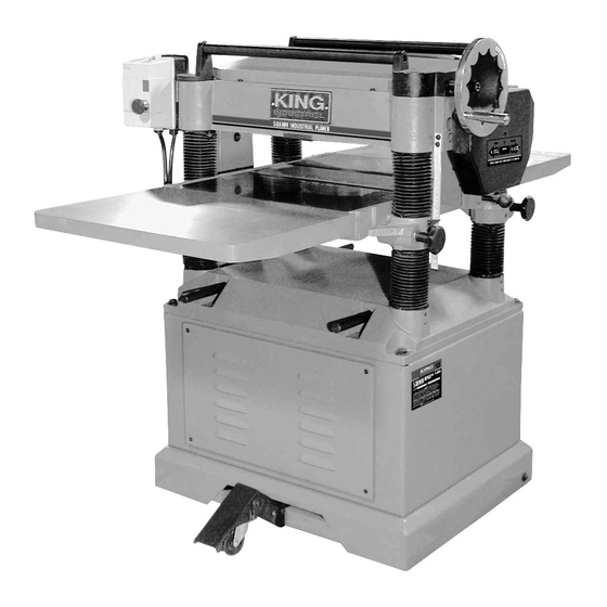
- Page 1 508MM INDUSTRIAL PLANER INSTRUCTION MANUAL MODEL: KC-520C-CE COPYRIGHT © 2015 ALL RIGHTS RESERVED BY KING CANADA TOOLS INC.
-
Page 2: Warranty Information
PARTS LIST WARRANTY INFORMATION MODEL: KC-520C-CE No. Part Order # Description No. Part Order # Description 2-YEAR LIMITED WARRANTY FOR THIS MACHINE Bearing 4505202100 Washer 4505201810 4505202110 Motor 4505201820 Oil seal 4505202120 Washer 4505201830 Sprocket PROOF OF PURCHASE 4505201840 4505202130 Hex. - Page 3 GENERAL & SPECIFIC SAFETY INSTRUCTIONS MODEL: KC-520C-CE VOLTAGE WARNING: Before connecting the tool to a power source (receptacle, outlet, etc.) be sure the voltage supplied is the same as that specified on the nameplate of the tool. A power source with voltage greater than that for the specified tool can result in SERIOUS No.
-
Page 4: Technical Information
TECHNICAL INFORMATION & PARTS LIST GETTING TO KNOW YOUR PLANER MODEL: KC-520C-CE TECHNICAL INFORMATION No. Part Order # Description No. Part Order # Description Motor ..................................3HP, 230V, 1 Phase, 50Hz Cutting Capacities: 4505200010 Head casting 4505200460 Adjusting shaft Minimum Length of unbutted stock ............................171mm (6.74”) -
Page 5: Electrical Information
CABINET & GEAR BOx PARTS DIAGRAM ELECTRICAL INFORMATION MODEL: KC-520C-CE WARNING! ALL ELECTRICAL CONNECTIONS MUST BE DONE BY A QUALIFIED ELECTRICIAN. FAILURE TO COMPLY MAY RESULT IN SERIOUS INJURY! ALL ADJUSTMENTS OR REPAIRS MUST BE DONE WITH THE MACHINE DISCONNECTED FROM THE POWER SOURCE. -
Page 6: Unpacking And Cleanup
UNPACKING & TABLE & COLUMN PARTS DIAGRAM MOVING YOUR PLANER MODEL: KC-520C-CE UNPACKING AND CLEANUP To ensure maximum performance from your planer, clean it properly and install it accurately before use. As soon as you receive the planer, we recommend you follow these procedures : 1. -
Page 7: Assembly And Adjustments
HEAD PARTS DIAGRAM ASSEMBLY & ADJUSTMENTS MODEL: KC-520C-CE ASSEMBLING AND ALIGNING MOTOR, MOTOR PULLEY AND BELTS 1. Assemble the motor to the motor mounting plate, as shown in Fig.5. NOTE : It is very important that the motor be mounted to motor plate by using the mounting hardware (A) Fig.5. - Page 8 Your planer is supplied with two table rollers (A) Fig.9, which aid in feeding the stock by reducing friction and turn as the stock is fed through the planer. Lubrication Guide for Industrial Planer KC-520C-CE It is not possible to give exact dimensions on the proper height setting of the table rollers because each type of wood behaves differently.
- Page 9 ASSEMBLY & ADJUSTMENTS ASSEMBLY & ADJUSTMENTS CONTROLLING THE DEPTH OF CUT FEED SPEED CONTROL The cutting depth scale (A) Fig.13 includes a combination of inch/metric Your planer is equipped with a spiral, serrated infeed roller and a solid steel measurements with a cutting range from 0 - 203mm (0” to 8”). The upward outfeed roller.
-
Page 10: Anti-Kickback Fingers
ASSEMBLY & ADJUSTMENTS ASSEMBLY & ADJUSTMENTS ADJUSTING INFEED AND OUTFEED ROLLER SPRING TENSION CHECKING WORK TABLE PARALLEL TO CUTTERHEAD To adjust the spring tension of the infeed and outfeed roller, using a hex. The work table is set parallel to the cutterhead at the factory and no further key, turn set screw (A) Fig.22 to adjust the infeed roller spring tension and adjustment should be necessary.