
Related Manuals for King Industrial KC-382CFX


Summary of Contents for King Industrial KC-382CFX
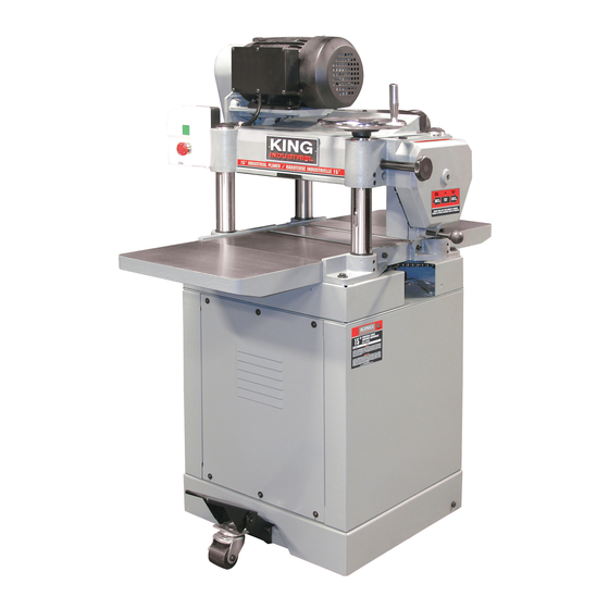
- Page 1 03/2013 15” INDUSTRIAL PLANER MODEL: KC-382CFX INSTRUCTION MANUAL COPYRIGHT © 2013 ALL RIGHTS RESERVED BY KING CANADA TOOLS INC.
-
Page 2: Warranty Information
WARRANTY INFORMATION 2-YEAR KING CANADA TOOLS LIMITED WARRANTY OFFERS A 2-YEAR LIMITED WARRANTY FOR COMMERCIAL USE. FOR THIS 15” PLANER PROOF OF PURCHASE Please keep your dated proof of purchase for warranty and servicing purposes. REPLACEMENT PARTS Replacement parts for this product are available at our authorized King Canada service centers across Canada. LIMITED TOOL WARRANTY King Canada makes every effort to ensure that this product meets high quality and durability standards. -
Page 3: General Safety Instructions For Power Tools
GENERAL SAFETY INSTRUCTIONS FOR POWER TOOLS 1. KNOW YOUR TOOL 12. ALWAYS WEAR SAFETY GLASSES. Read and understand the owners manual and labels affixed to Always wear safety glasses (ANSI Z87.1). Everyday eyeglasses only have impact resistant lenses, that are NOT the tool. -
Page 4: Electrical Information
ELECTRICAL INFORMATION WARNING! ALL ADJUSTMENTS OR REPAIRS MUST BE DONE WITH THE PLANER DISCONNECTED FROM THE POWER SOURCE. FAILURE TO COMPLY MAY RESULT IN SERIOUS INJURY! GENERAL INFORMATION- 220V single phase operation This planer comes with a 3 HP 220V single phase motor which draws 18 amps under maximum load. -
Page 5: Specifications
17. Serrated infeed roller 18. Chip breaker 19. Cutterhead 20. Outfeed roller SPECIFICATIONS KC-382CFX 15” INDUSTRIAL PLANER TECHNICAL INFORMATION Motor ..............................3HP, 240V, 18Amp.,1 Phase, 60Hz Power transfer ....................................3 V-belts Capacities: Minimum Length of unbutted stock................................8” Maximum width of stock ..................................15”... - Page 6 ASSEMBLY ASSEMBLING WHEEL ASSEMBLY TO CABINET 1. Position the wheel assembly (A) Fig.4 in between the mounted bracket (B). Align the mounting holes and secure wheel assembly to bracket using a long hex. bolt and nylon hex. nut. Do not overtighten. 2.
-
Page 7: Depth Of Cut Adjustment
ADJUSTMENTS & OPERATION CLEANUP BEFORE OPERATION The unpainted surfaces of the planer are coated with a protective grease to prevent corrosion during shipment. This protective coating must be removed using a solvent cleaner or degreaser. For best performance, make sure you clean all moving parts or sliding contact surfaces that are coated. -
Page 8: Anti-Kickback Fingers
ADJUSTMENTS & OPERATION ANTI-KICKBACK FINGERS A series of anti-kickback fingers (A) Fig.12 are provided on the infeed end of the planer. These prevent kickback of workpiece during the planing operation. These anti-kickback fingers operate by gravity and no adjustment is required. It is necessary, however, to inspect them occasionally to make sure they are free of gum and pitch and that they move independently and operate correctly. - Page 9 ADJUSTMENTS & OPERATION CHECKING, ADJUSTING AND REPLACING KNIVES To check, adjust or replace the planer knives, proceed as follows: 1. DISCONNECT THE MACHINE FROM THE POWER SOURCE. 2. Remove the top cover (A) Fig.15 and the 4” dust chute (B). FIGURE 15 3.
- Page 10 ADJUSTMENTS & OPERATION CHECKING, ADJUSTING AND REPLACING KNIVES continued... C. If any of the knives require an adjustment, slightly loosen the knife locking bar (A) Fig.19 in each of the knife slots by turning the five locking screws (B) clockwise into the locking bar just enough to relieve stress in the cutterhead but not disturb the setting of the knives.
- Page 11 ADJUSTMENTS & OPERATION ADJUSTING HEIGHT OF CHIPBREAKER The chipbreaker extends down around the front of the cutterhead and raises as stock is fed through the planer. The chipbreaker “breaks or curls” the chips as they leave the cutterhead and the bottom edge of the chipbreaker helps hold the stock flat down on the table during the planing operation.
- Page 12 ADJUSTMENTS & OPERATION ADJUSTING HEIGHT OF INFEED ROLLER The infeed roller is adjusted at the factory at 0.040” below the cutting circle. To check and adjust the height of infeed roller, proceed as follows: 1. DISCONNECT THE MACHINE FROM THE POWER SOURCE. 2.
- Page 13 ADJUSTMENTS & OPERATION ADJUSTING SPRING TENSION OF INFEED AND OUTFEED ROLLERS The infeed and outfeed rollers are those parts of your planer that feed the stock while it is being planed. The feed rollers are under spring tension and this tension must be sufficient to feed the stock uniformly through the planer without slipping but should not be too tight that it causes damage to the board.
-
Page 14: Adjusting Cutterhead Parallel To Table
ADJUSTMENTS & OPERATION ADJUSTING CUTTERHEAD PARALLEL TO TABLE The cutterhead is set parallel to the table at the factory and no further adjustment should be necessary. If your machine is planing a taper, first check to see if the knives are set properly in the cutterhead. Then check to see if the cutterhead is set parallel to the table as follows: 1. - Page 15 LUBRICATION & MAINTENANCE LUBRICATION The gear box oil should be changed after the first 20 hours of operation as part of the normal break-in procedure, and then once a year using automotive grade gear oil (80W-90W). The gear box drain plug (A) Fig.34 is located at the bottom of the gear box.
-
Page 16: Troubleshooting
TROUBLESHOOTING Problem Probable cause Probable solution Motor will not start. 1. Open circuit in motor. 1. Inspect all motor leads for loose or open connections. 2. Starting capacitor is at fault. 2. Test/replace starting capacitor. Motor does not develop full 1.