
Related Manuals for King Industrial KC-630FX-2


Summary of Contents for King Industrial KC-630FX-2
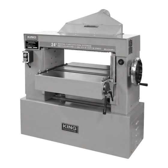
- Page 1 24” INDUSTRIAL PLANER WITH SPIRAL CUTTERHEAD MODEL: KC-630FX-2 (220V-440V) INSTRUCTION MANUAL MODEL: KC-630FX-6 (600V) COPYRIGHT © 2017 ALL RIGHTS RESERVED BY KING CANADA TOOLS INC.
-
Page 2: Warranty Information
WARRANTY INFORMATION 2-YEAR kING CANADA TOOLS LIMITED WARRANTY OFFERS A 2-YEAR LIMITED WARRANTY FOR THIS 24” INDUSTRIAL PLANER INTENDED FOR NON COMMERCIAL USE PROOF OF PURCHASE Please keep your dated proof of purchase for warranty and servicing purposes. PARTS DIAGRAM & PARTS LISTS Refer to the Parts section of the King Canada web site for the most updated parts diagram and parts list. - Page 3 GENERAL & SPECIFIC SAFETY RULES 1. kNOW YOUR TOOL watch) because they could get caught in moving parts. Non-slip Read and understand the owners manual and labels affixed to the footwear is recommended. Wear protective hair covering to contain tool. Learn its application and limitations as well as its specific long hair.
- Page 4 14) Spiral cutterhead 6) Top safety cover 15) 3 V-belt drive system 7) Lifting anchor point (1 of 2) 16) Variable feed speed control 8) Table raising/lowering handwheel Specifications MODEL kC-630FX-2 kC-630FX-6 Maximum planing width 24” 24” Maximum planing thickness 8” 8”...
-
Page 5: Electrical Information
DONE WITH THE MACHINE DISCONNECTED FROM THE POWER SOURCE. FAILURE TO COMPLY MAY RESULT IN SERIOUS INJURY! WIRING AND POWER SUPPLY WARNING: THIS PLANER IS AVAILABLE WITH A 220V-440V, 3 PHASE MOTOR (MODEL KC-630FX-2) OR A 600V, 3 PHASE MOTOR (MODEL KC-630FX-6). NOTE: A power cord and plug is not supplied with this planer. -
Page 6: Unpacking And Assembly
UNPACkING & ASSEMbLY UNPACkING AND CLEANUP WARNING! TO REDUCE THE POTENTIAL FOR PERSONAL INJURY AND/OR DAMAGE TO THE MACHINE, BEFORE ASSEMBLING MAKE SURE THE MACHINE IS TURNED OFF. DO NOT TURN ON THE MACHINE UNTIL INSTRUCTED TO DO SO AFTER ALL ASSEMBLY STEPS IN THIS MANUAL HAVE BEEN COMPLETED. - Page 7 ADJUSTMENTS & OPERATION SETTING THE DEPTH OF CUT The depth of cut is set by raising and lowering the table. To adjust the depth of cut: 1. First loosen the table lock knob (A) Fig.2 by turning it counterclockwise. 2. Rotate the handwheel (B) to raise or lower the table. 3.
- Page 8 ADJUSTMENTS & OPERATION USING AND ADJUSTING TAbLE ROLLERS continued... If an adjustment is necessary: 4. Loosen the hex. nut (B) Fig.9 located underneath the table below the infeed roller (A). Note: It will be necessary to raise the table in order to gain access to the the hex. nut. 5.
- Page 9 ADJUSTMENTS & OPERATION INSPECTING AND CLEANING ANTI-kICkbACk FINGERS Anti-kickback fingers (A) Fig.13 are provided for your safety to prevent workpiece kickbacks. These fingers operate by gravity and it is necessary to inspect them oc- casionally to make sure they are free of gum and pitch so that they can move independently and operate correctly.
- Page 10 ADJUSTMENTS & OPERATION ADJUSTING THE CHIPbREAkER ASSEMbLY continued... 5. If the chipbreaker assembly needs to be adjusted: Loosen the two hex. nuts (A) Fig.17 (at each end of the chipbreaker), and rotate the adjustment cap screws (B) using a hex. key until the chipbreaker assembly is just touching the top of the gauge block at both ends of the chipbreaker assembly.
- Page 11 ADJUSTMENTS & OPERATION ADJUSTING OUTFEED ROLLER continued... 5. If the outfeed roller needs to be adjusted: Loosen the hex. nut (A) Fig.21, and rotate the adjustment cap screw (B) using a hex. key until the outfeed roller is just touching the top of the gauge block at one end of the table. Retighten the hex.
-
Page 12: Adjusting Table Gibs
ADJUSTMENTS & OPERATION ADJUSTING TAbLE HEIGHT SCALE The table height scale on the right side of the Planer indicates the distance from the table and the “cutting circle”. To check and adjust the scale: 1. Run a piece of wood through the Planer, and turn off the machine. 2. -
Page 13: Periodic Maintenance Checklist
MAINTENANCE MAINTENANCE WARNING! TO REDUCE THE POTENTIAL FOR PERSONAL INJURY MAKE SURE THE MACHINE IS TURNED OFF BEFORE PERFORMING ANY MAINTENANCE OPERATIONS. REGULAR MAINTENANCE CHECkLIST 1. Make sure that everything has been installed properly. Check to make sure that all parts are secured properly before using the machine. 2.