
Related Manuals for King Industrial KC-526FX


Summary of Contents for King Industrial KC-526FX
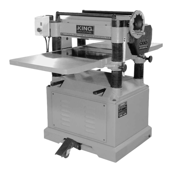
- Page 1 20” INDUSTRIAL PLANER WITH SPIRAL CUTTERHEAD MODEL: KC-526FX INSTRUCTION MANUAL COPYRIGHT © 2020 ALL RIGHTS RESERVED BY KING CANADA TOOLS INC.
-
Page 2: Warranty Information
WARRANTY INFORMATION 2-YEAR KING CANADA TOOLS LIMITED WARRANTY OFFERS A 2-YEAR LIMITED WARRANTY FOR THIS 20” PLANER FOR COMMERCIAL USE. PROOF OF PURCHASE Please keep your dated proof of purchase for warranty and servicing purposes. REPLACEMENT PARTS Replacement parts for this product are available at our authorized King Canada service centers across Canada. Please use the 10 digit part numbers listed in this manual for all part orders where applicable. -
Page 3: Specific Safety Instructions
GENERAL & SPECIFIC SAFETY INSTRUCTIONS VOLTAGE WARNING: Before connecting the tool to a power source (receptacle, outlet, etc.) be sure the voltage supplied is the same as that specified on the nameplate of the tool. A power source with voltage greater than that for the specified tool can result in SERIOUS INJURY to the user - as well as damage to the tool. -
Page 4: Technical Information
TECHNICAL INFORMATION & GETTING TO KNOW YOUR PLANER TECHNICAL INFORMATION Motor ..................................5HP, 220V, 1 Phase, 60Hz Cutting Capacities: Minimum Length of unbutted stock ..............................6.74” Maximum width of stock ..................................20” Maximum Thickness of stock ..................................8” Planing depth (width under 8.3”) ..............................Max- 0.23” Planing depth (width from 8.3”-20”) ............................Max- 0.12”... -
Page 5: Electrical Connections
ELECTRICAL CONNECTIONS (30 AMP. CIRCUIT) WARNING! ALL ELECTRICAL CONNECTIONS MUST BE DONE BY A QUALIFIED ELECTRICIAN. FAILURE TO COMPLY MAY RESULT IN SERIOUS INJURY! ALL ADJUSTMENTS OR REPAIRS MUST BE DONE WITH THE MACHINE DISCONNECTED FROM THE POWER SOURCE. FAILURE TO COMPLY MAY RESULT IN SERIOUS INJURY! POWER SUPPLY WARNING: YOUR PLANER MUST BE CONNECTED TO A 220V, 30 AMP. -
Page 6: Unpacking And Cleanup
UNPACKING & MOVING YOUR PLANER UNPACKING AND CLEANUP To ensure maximum performance from your planer, clean it properly and install it accurately before use. As soon as you receive the planer, we recommend you follow these procedures : 1. Inspect packing crate for damage in transit. Record damage and report it immediately to shipper. -
Page 7: Assembly And Adjustments
ASSEMBLY & ADJUSTMENTS ASSEMBLING AND ALIGNING MOTOR, MOTOR PULLEY AND BELTS 1. Assemble the motor to the motor mounting plate, as shown in Fig.5. NOTE : It is very important that the motor be mounted to motor plate by using the mounting hardware (A) Fig.5. 2. -
Page 8: Adjusting Table Rollers
ASSEMBLY & ADJUSTMENTS ADJUSTING TABLE ROLLERS Your Planer is supplied with two table rollers (A) Fig.9, which aid in feeding the stock by reducing friction and turn as the stock is fed through the Plan- er. It is not possible to give exact dimensions on the proper height setting of the table rollers because each type of wood behaves differently. - Page 9 ASSEMBLY & ADJUSTMENTS CONTROLLING THE DEPTH OF CUT The cutting depth scale (A) Fig.13 includes a combination of inch/metric measurements with a cutting range from 0” to 8”. The upward or downward movement is controlled by the handwheel (B). One turn of the handwheel will increase or decrease the height by 0.059”...
-
Page 10: Checking Work Table Parallel To Cutterhead
ASSEMBLY & ADJUSTMENTS CHECKING WORK TABLE PARALLEL TO CUTTERHEAD The work table is set parallel to the cutterhead at the factory and no further adjustment should be necessary. If your Planer is planing a taper, first check to see if the knives are set properly in the cutterhead, proceed as follows;... -
Page 11: Anti-Kickback Fingers
ASSEMBLY & ADJUSTMENTS ADJUSTING INFEED AND OUTFEED ROLLER SPRING TENSION To adjust the spring tension of the infeed and outfeed roller, using a hex. key, turn screw (A) Fig.22 to adjust the infeed roller spring tension and screw (B) to adjust the outfeed roller spring tension. Make sure that both sides are adjusted evenly or else you will get uneven feeding of stock. -
Page 12: Feed Speed Control
ASSEMBLY & ADJUSTMENTS FEED SPEED CONTROL Your Planer is equipped with a spiral, serrated infeed roller and a solid steel outfeed roller. When the feed rollers are engaged, they turn to feed stock. The feed rollers slow down automatically when the Planer is under heavy load. -
Page 13: Parts Diagram & Parts Lists
Below you will find lubrication instructions and maintenance intervals to maintain your Planer in good working order. Failure to upkeep your Planer as prescribed on this page will reduce its life span. Lubrication Guide for 20” Industrial Planer KC-526FX Position...