
Related Manuals for King Industrial KC-530FXR


Summary of Contents for King Industrial KC-530FXR
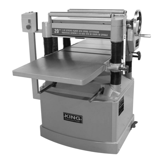
- Page 1 20” 5HP EXTREME PLANER WITH SPIRAL CUTTERHEAD MODEL: KC-530FXR INSTRUCTION MANUAL COPYRIGHT © 2008 ALL RIGHTS RESERVED BY KING CANADA TOOLS INC.
-
Page 2: Warranty Information
WARRANTY INFORMATION 2-YEAR KING CANADA TOOLS LIMITED WARRANTY OFFERS A 2-YEAR LIMITED WARRANTY FOR THIS 20” EXTREME PLANER FOR INDUSTRIAL USE. PROOF OF PURCHASE Please keep your dated proof of purchase for warranty and servicing purposes. REPLACEMENT PARTS Replacement parts for this product are available at our authorized King Canada service centers across Canada. LIMITED TOOL WARRANTY King Canada makes every effort to ensure that this product meets high quality and durability standards. - Page 3 GENERAL & SPECIFIC SAFETY INSTRUCTIONS VOLTAGE WARNING: Before connecting the machine to a power source (receptacle, outlet, etc.) be sure the voltage supplied is the same as that specified on the nameplate of the tool. A power source with voltage greater than that for the specified tool can result in SERIOUS INJURY to the user - as well as damage to the machine motor.
-
Page 4: Technical Information
TECHNICAL INFORMATION & GETTING TO KNOW YOUR PLANER TECHNICAL INFORMATION Model ......................................KC-530FXR Motor ..............................5HP, 220V, 30 Amps., 1 Phase, 60Hz WARNING! This 20” extreme planer must be connected to a 40 amp circuit breaker to be operated at 220V. See electrical information on the following page. - Page 5 ELECTRICAL CONNECTIONS & CONTROLS WARNING! ALL ELECTRICAL CONNECTIONS MUST BE DONE BY A QUALIFIED ELECTRICIAN. FAILURE TO COMPLY MAY RESULT IN SERIOUS INJURY! ALL ADJUSTMENTS OR REPAIRS MUST BE DONE WITH THE MACHINE DISCONNECTED FROM THE POWER SOURCE. FAILURE TO COMPLY MAY RESULT IN SERIOUS INJURY! POWER SUPPLY WARNING!: THIS PLANER MUST BE CONNECTED TO A 220V, 40 AMP.
-
Page 6: Unpacking And Cleanup
UNPACKING, CLEANING & MOVING YOUR PLANER UNPACKING AND CLEANUP To ensure maximum performance from your planer, clean it properly and install it accurately before use. As soon as you receive the planer, we recommend you follow these procedures : 1) Inspect packing crate for damage in transit. Record damage and report it immediately to transport carrier. - Page 7 ASSEMBLY ASSEMBLING SOLID EXTENSION TABLES 2 Solid extension tables are supplied and can be assembled to the front and back of your planer table. To install either extension table (A) Fig.5, hold the extension table against the front of the table and using 3 hex. bolts (B) Fig.5, fix the extension table to the table.
- Page 8 PRE-OPERATION & ADJUSTMENTS CHECKING GEAR BOX OIL LEVEL Before you start your planer for the first time, it is very important to check the oil level of the gear box. The proper oil level is just flush with the oil level hole.
-
Page 9: Basic Operation
1) Change gear box oil. IMPORTANT NOTE: The gear box oil must be changed after the first 20 hours of operation your new planer. Lubrication Guide for 20” Exteme Planer KC-530FXR Below you will find lubrication instructions and maintenance intervals to maintain your planer in good working order. Failure to upkeep your planer as prescribed on this page will reduce its life span. -
Page 10: Maintenance And Adjustments
MAINTENANCE & ADJUSTMENTS CHANGING GEAR BOX OIL The gear box oil must be changed after the first 20 hours of operating your new planer. After the first 20 hours, the gear box oil should only be changed yearly or after 2,500 hours of operation. To change the gear box oil;... - Page 11 MAINTENANCE & ADJUSTMENTS MOTOR AND CUTTERHEAD PULLEY ALIGNMENT Proper pulley alignment is important to prevent premature belt wear. This means both the motor and cutterhead pulleys must be parallel to each other. Use a straight edge ruler to check pulley alignment. If you find that the pulleys are out of alignment;...
-
Page 12: Adjusting Chain Tension
MAINTENANCE & ADJUSTMENTS ADJUSTING ROLLERS, CHIPBREAKER AND PRESSURE BAR HEIGHT USING WOOD BLOCKS AND A FEELER GAUGE continued... Infeed Roller adjustment; 7) Loosen the infeed roller adjustment hex. nuts (A) Fig.19 and turn the adjustment set screws (B) at each end to raise the infeed roller above the wood blocks. - Page 13 MAINTENANCE, ADJUSTMENTS & TROUBLESHOOTING ADJUSTING CHIP DEFLECTOR POSITION The chip deflector (A) Fig.23 prevents chips from getting onto the outfeed roller. To adjust the chip deflector position; 1) Disconnect the planer from the power source. 2) Remove the dust hood and top cover. 3) Loosen the 3 chip deflector flange hd hex.