Advertisement
Quick Links
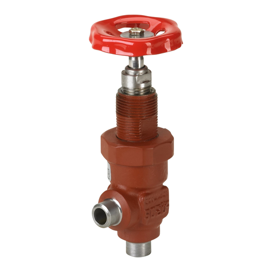
Installation guide
Shut-off valves
SVA-S 6-10
2a
1
5a
4a
4b
6
7
10
© Danfoss | DCS (nb) | 2020.03
2b
3
Max. Nm
65 (+/- 5)
5b
5c
Max. Nm
Max. LB-feet
30
22
9
8
11
AN046686419206xx-000601 | 1
ENGLISH
Installation
Refrigerants
Applicable to HCFC, HFC, R717 (Ammonia),
R744 (CO2) and all flammable refrigerants.
The valve is only recommended for use in closed circuits. For further
information please contact Danfoss.
Temperature range
–60°C to +150°C (–76°F to +302°F)
Pressure range
The valves are designed for a max. working pressure of 52 bar g (754 psig).
Installation
The valve must be installed with the spindle vertically upwards or in
horizontal position (fig. 1). Valves should be opened by hand (fig. 3)
according to the guidelines in the datasheet. The valve is designed to
withstand a high internal pressure. However, the piping system should be
designed to avoid liquid traps and reduce the risk of hydraulic pressure
caused by thermal expansion. It must be ensured that the valve is
protected from pressure transients like "liquid hammer" in the system.
Recommended flow direction
Direct the flow towards the cone as indicated by the arrow placed on the
valve housing (fig. 2). The force used to open and close the valve must
not exceed the force of an ordinary handwheel.
Welding
The bonnet should be removed before welding (fig. 4) to prevent damage
to the sealing parts in the packing gland and between the valve body
and bonnet, as well as the teflon gasket in the valve seat. Be careful not
Max. LB-feet
to damage the teflon cone ring and make sure the complete bonnet is
protected from dirt and water while removed.
59
Removing the bonnet can be omitted provided that: The temperature
in the area between the valve body and bonnet during welding does
not exceed +150°C/+302°F. This temperature depends on the welding
method as well as on any cooling of the valve body during the welding
itself. (Cooling can be ensured by, for example, wrapping a wet cloth
around the valve body.) Make sure that no dirt, welding debris etc. get
into the valve during the welding procedure
Only materials and welding methods, compatible with the valve housing
material, must be welded to the valve housing. The valve housing must
be free from stresses (external loads) after installation.
The valve should be cleaned internally to remove welding debris on
completion of welding and before the valve is reassembled. Avoid
welding debris and dirt in the threads of the housing and the bonnet.
Do NOT remove or service the dark colored grease between the spindle
thread and the bonnet. In case the grease has been contaminated with
dirt, debris, particles or water the complete top part must be replaced.
Stop valves must not be mounted in systems where the outlet side of
the valve is open to atmosphere. The outlet side of the valve must always
be connected to the system or properly capped off, for example with a
welded-on end plate.
Assembly
Remove welding debris and any dirt from pipes and valve body before
assembly. Check that the cone has been fully screwed back towards the
bonnet before it is replaced in the valve body (fig. 5).
Tightening
Tighten the bonnet with a torque wrench, to the values indicated in
the table (fig. 5).
Colours and identification
The SVA valves are painted with a red primer in the factory. Precise
identification of the valve is made via the red coloured ID ring at the top
of the bonnet, as well as by the stamping on the valve body. The external
surface of the valve housing must be prevented against corrosion with a
suitable protective coating after installation and assembly.
Protection of the ID ring when repainting the valve is recommended.
© Danfoss | DCS (nb) | 2020.03
Maintenance
Packing gland
When per forming ser vice and main-tenance, replace the
complete packing gland only, which is available as a spare
part. As a general rule, the packing gland must not be removed
if there is internal pressure in the valve. However, if the
following pre-cautionary measures are taken, the packing gland can be
removed with the valve still under pressure:
Backseating (fig. 6)
To backseat the valve, turn the spindle counter-clockwise until the
valve is fully open.
Pressure equalization (fig. 7)
In some cases, pressure forms behind the packing gland. Hence a
handwheel or similar should be fastened on top of thespindle while
the pressure is equalized. The pressure can be equalized by slowly
screwing out the gland.
Removal of packing gland (fig. 8)
Cap and packing gland can now be removed.
Dismantling the valve
Do not remove the bonnet while the valve is still under pressure.
-
Check that the alu-ring (fig. 10, pos. A) has not been visibly de-
formed.
-
Check that the spindle is free of scratches and impact marks.
-
If the teflon cone ring has been damaged, the whole cone assem-
bly must be replaced.
Replacement of the cone (fig. 11)
Unscrew the cone screw (pos. D) with an
Allen key.
SVA-S 6-10 .................................................................................... 2.0 mm A/F
(An Allen key is included in the Danfoss Industrial Refrigeration gasket
set).
Remove the balls (pos. E).
Number of balls in fig. 11, pos. E:
SVA-S 6-10 ................................................................................................6 pcs.
The cone can then be removed. Place the new cone on the spindle
and replace the balls. Refit the cone screw in again using Loctite No.
648. to ensure that the screw is properly fastened.
Do NOT remove or service the dark colored grease between the spindle
thread and the bonnet. In case the grease has been contaminated with
dirt, debris, particles or water the complete top part must be replaced.
Assembly
Remove any dirt from the body before the valve is assembled. Check
that the cone has been screwed back towards the bonnet before it is
replaced in the valve body (fig. 5).
Tightening
Tighten the bonnet with a torque wrench, to the values indicated in the
table (fig. 5). Tighten the packing gland with a torque wrench, to the
values indicated in the table (fig. 9).
Use only original Danfoss parts, including packing glands, O-rings and
gaskets for replacement. Materials of new parts are certified for the
relevant refrigerant.
In cases of doubt, please contact Danfoss.
Danfoss accepts no responsibility for errors and omissions. Danfoss
Industrial Refrigeration reserves the right to make changes to
products and specifications without prior notice.
AN046686419206xx-000601 | 2
Advertisement

Related Manuals for Danfoss SVA-S 6-10


Summary of Contents for Danfoss SVA-S 6-10
- Page 1 Removing the bonnet can be omitted provided that: The temperature in the area between the valve body and bonnet during welding does (An Allen key is included in the Danfoss Industrial Refrigeration gasket not exceed +150°C/+302°F. This temperature depends on the welding set).
-
Page 2: Entretien
Le capuchon peut seulement rester en place si, pendant le soudage, Une clé Allen est fournie dans le jeu de joints d’étanchéité Danfoss Industrial elementos de sellado situados en el prensaestopas y entre el cuerpo y Compruebe que el eje no presente arañazos ni marcas de golpes... - Page 3 (Una chiave allen è inclusa nel set delle guarnizioni Danfoss Industrial nos o-rings e vedações nas gaxetas e entre o corpo da válvula e a tampa, SVA-S 6-10 ..................
- Page 4 使用艾伦内六角扳手拧松阀锥螺钉(位置 D)。 损坏。 请小心,不要损坏特氟龙阀芯,并确保阀盖在 Refrigeration). uszczelki w gnieździe zaworu. Należy zachować ostrożność, aby nie SVA-S 6-10 ............2 . 0 毫 米 A / F Wyjąć kulki (poz. E). uszkodzić teflonowego pierścienia stożkowego, oraz upewnić się, czy 取下时不会沾到土和水。 podczas demontażu pokrywa jest chroniona przed kurzem i wodą.
- Page 5 SVA-S 6-10 ....................2 , 0 м м (рис. 4), чтобы избежать повреждения уплотнительных колец и тефлоновых уплотнений функционального модуля. Осторожно, не (Торцевой ключ включен в сервисный комплект подразделения Danfoss повредите тефлоновое уплотнение. Необходимо обеспечить защиту Industrial Refrigeration). снятого функционального модуля от грязи и воды.