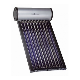
Viessmann Vitosol 222-T Installation And Service Instructions For Contractors
Vacuum tube collector and dhw cylinder
Hide thumbs
Also See for Vitosol 222-T:
- Installation instructions manual (24 pages) ,
- Operating instructions for the system user (16 pages)

Related Manuals for Viessmann Vitosol 222-T


Summary of Contents for Viessmann Vitosol 222-T
- Page 1 VIESMANN Installation and service instructions for contractors Vitosol 222-T Type BS2A Vacuum tube collector and DHW cylinder For applicability, see the last page VITOSOL 222-T Please keep safe. 5516 344 GB 2/2014...
- Page 2 Repairing components that fulfil a ■ Statutory regulations regarding the safety function can compromise prevention of accidents the safe operation of your sys- ■ Statutory regulations regarding envi- tem. ronmental protection Defective components must be replaced with genuine Viessmann spare parts.
- Page 3 Installing non-author- ised components and making non-approved modifications or conversions can compromise safety and may invalidate our warranty. For replacements, use only orig- inal spare parts supplied or approved by Viessmann.
-
Page 4: Table Of Contents
Index Index Installation instructions Preparing for installation Observe prior to installation.................. Installation sequence Installing the collector (positioning at 90°)............Installing the collector (positioning at 75 °)............14 Angle of inclination of the absorbers..............22 Installing the DHW cylinder.................. 22 Connecting the solar lines..................28 Installing the control unit.................. -
Page 5: Preparing For Installation
Preparing for installation Observe prior to installation Vacuum tube collector ■ Do not install the collectors when there Viessmann recommends the following is strong sunlight. (see table): ■ When installing in regions where low temperatures are to be expected, fill the solar thermal system with anti- freeze. - Page 6 Preparing for installation Observe prior to installation (cont.) ■ Ensure that the floors below are not damaged in the event of a leak in the DHW cylinder or pipe connections.
-
Page 7: Installing The Collector (Positioning At 90°)
Installation sequence Installing the collector (positioning at 90°) Please note Note Do not damage the vacuum On balconies with a protruding floor tubes. plate, observe the following clearances Do not position the cardboard between the floor plate and the lower packaging vertically, do not sub- holes: ject it to impacts and do not walk... - Page 8 Installation sequence Installing the collector (positioning at 90°) (cont.)
- Page 9 Installation sequence Installing the collector (positioning at 90°) (cont.) Ø 14 Adjusting the angle of inclination of the absorbers Adjust the angle of inclination with the collector still in its packaging.
- Page 10 Installation sequence Installing the collector (positioning at 90°) (cont.) Perform the adjustment by rotating the vacuum tubes (use the adjustment tem- plate provided). Note The coated (blue) side of the absorber must be aligned with the sun. For the absorber angles of inclination, see the table on page 22.
- Page 11 Installation sequence Installing the collector (positioning at 90°) (cont.)
- Page 12 Installation sequence Installing the collector (positioning at 90°) (cont.)
- Page 13 Installation sequence Installing the collector (positioning at 90°) (cont.) Please note Protect the vacuum tube collector The vacuum tube collector may from insolation with a tarpaulin be damaged if the solar thermal (accessories). system is not filled with heat transfer medium immediately after installation.
-
Page 14: Installing The Collector (Positioning At 75 °)
Installation sequence Installing the collector (positioning at 75 °) Please note Install the collector with a fall (min. 2°), Do not damage the vacuum i.e. the header casing must be in a higher tubes. position. Do not position the cardboard packaging vertically, do not sub- ject it to impacts and do not walk on it. - Page 15 Installation sequence Installing the collector (positioning at 75 °) (cont.)
- Page 16 Installation sequence Installing the collector (positioning at 75 °) (cont.)
- Page 17 Installation sequence Installing the collector (positioning at 75 °) (cont.) Ø 14 Adjusting the angle of inclination of the absorbers Adjust the angle of inclination with the collector still in its packaging.
- Page 18 Installation sequence Installing the collector (positioning at 75 °) (cont.) Perform the adjustment by rotating the vacuum tubes (use the adjustment tem- plate provided). Note The coated (blue) side of the absorber must be aligned with the sun. For the absorber angles of inclination, see the table on page 22.
- Page 19 Installation sequence Installing the collector (positioning at 75 °) (cont.)
- Page 20 Installation sequence Installing the collector (positioning at 75 °) (cont.)
- Page 21 Installation sequence Installing the collector (positioning at 75 °) (cont.) Please note Cover the vacuum tube collector Installing the vacuum tube collec- with a tarpaulin (accessories) tor and commissioning the solar and keep it covered until heat thermal system without first transfer has been regulated.
-
Page 22: Angle Of Inclination Of The Absorbers
Installation sequence Angle of inclination of the absorbers Latitude Year-round use Winter use Positioning angle of collec- Positioning angle of collec- 75° 90° 75° 90° Angle of inclination of the absorbers 18° 63° — 36° — 20° 61° — 33° —... - Page 23 Installation sequence Installing the DHW cylinder (cont.) Clearance between DHW cylinder and vacuum tube collector A DHW cylinder B Vacuum tube collector...
- Page 24 Installation sequence Installing the DHW cylinder (cont.) Wall clearances Note If the dimensions cannot be adhered to, position the side cover with the power cable so that is aligned with the window. Any service or maintenance work can then be done through the open window. DHW cylinders with different side cover layouts are available.
- Page 25 Installation sequence Installing the DHW cylinder (cont.) Ø 18...
- Page 26 Installation sequence Installing the DHW cylinder (cont.) Cylinder capacity in li- The connections must face down- wards. tres a in mm b in mm A Safety valve Discharge pipe to drainage system connection...
- Page 27 Installation sequence Installing the DHW cylinder (cont.) Connection piece WW Domestic hot water, G ½ Safety valve (T&P valve) (seal with braided sealing tape) HVs Heating water flow, solar thermal Discharge pipe to drainage system system, G ½ connection HRs Heating water return, solar thermal Fill valve system, G ½...
-
Page 28: Connecting The Solar Lines
Installation sequence Installing the DHW cylinder (cont.) Safety valve (T&P valve) Please note DHW with temperatures in Always install to protect the DHW cylin- excess of 60 °C can cause scald- der against excessive temperatures. ing. ■ Permissible operating pressure 6 bar. To limit the temperature to 60 °C, Max. - Page 29 Installation sequence Connecting the solar lines (cont.)
-
Page 30: Installing The Control Unit
Installation sequence Installing the control unit... -
Page 31: Electrical Connection
Installation sequence Electrical connection If the power cable needs to be extended: ■ For the electrical installation, observe the regulations regarding electrical specifications. ■ For the power cables, use waterproof, temperature-resistant, well insulated and hard-wearing cables: – Cable resistance ≥ 2 MΩ –... - Page 32 Installation sequence Electrical connection (cont.) E High limit safety cut-out (triggers at F Immersion heater 99 °C)
-
Page 33: Commissioning, Inspection, Maintenance
Commissioning, inspection, maintenance Steps - commissioning, inspection and maintenance For further information regarding the individual steps, see the page indicated Commissioning steps Inspection steps Maintenance steps Page • 1. Checking the DHW cylinder........... 34 • • • 2. Checking the electrical connections......34 •... -
Page 34: Further Details Regarding The Individual Steps
Commissioning, inspection, maintenance Further details regarding the individual steps Checking the DHW cylinder ■ Are the safety valves installed? ■ Has the hot water drain been installed so that any discharged hot water can- not represent a risk to individuals or damage the system and materials in or on the building? Checking the electrical connections... - Page 35 Commissioning, inspection, maintenance Further details regarding the individual steps (cont.) 5. Open fill tap (turn handle A by 90°). 6. Switch on fill pump. Note Operate fill pump until heat transfer medium runs out of the safety valve. 7. Close fill tap and switch off fill pump. 2.
- Page 36 Commissioning, inspection, maintenance Further details regarding the individual steps (cont.) Check the cable resistances in the plug Note with integral residual current device: If no resistance is measured, press the ■ Resistance between L and N 30 to reset button on the plug (see diagram 40 Ω...
-
Page 37: Fault
Fault Fault messages In the event of fault messages, the elec- tric heating is switched off. The operating buttons on the control unit are locked. The display shows the fault code. E5 is shown in the other areas. If the voltage drops below 150 V~, an alarm is trig- gered. -
Page 38: Specification
Specification Vacuum tube collector Number of tubes Absorber area 1.25 1.89 Total collector area 1.50 2.25 Weight (unfilled) Content, heat transfer me- litres dium Permiss. operating pres- sure Dimensions ■ Length 2260 2260 ■ Width 1070 ■ Height DHW cylinder Cylinder capacity 80 l 120 l... - Page 40 Applicability Serial No.: 7369432 7369435 7369434 7369436 Viessmann Werke GmbH&Co KG Viessmann Limited D-35107 Allendorf Hortonwood 30, Telford Telephone: +49 6452 70-0 Shropshire, TF1 7YP, GB Fax: +49 6452 70-2780 Telephone: +44 1952 675000 www.viessmann.com Fax: +44 1952 675040 E-mail: info-uk@viessmann.com...