Table of Contents
Advertisement
Quick Links
Advertisement
Table of Contents

Related Manuals for Grizzly T25937


Summary of Contents for Grizzly T25937
- Page 1 (For models manufactured since 03/16) COPYRIGHT © JULY, 2016 BY GRIZZLY INDUSTRIAL, INC. WARNING: NO PORTION OF THIS MANUAL MAY BE REPRODUCED IN ANY SHAPE OR FORM WITHOUT THE WRITTEN APPROVAL OF GRIZZLY INDUSTRIAL, INC. #JH18243 PRINTED IN INDIA V1.07.16...
- Page 2 This manual provides critical safety instructions on the proper setup, operation, maintenance, and service of this machine/tool. Save this document, refer to it often, and use it to instruct other operators. Failure to read, understand and follow the instructions in this manual may result in fire or serious personal injury—including amputation, electrocution, or death.
-
Page 3: Table Of Contents
Table of Contents INTRODUCTION ..........................2 Manual Accuracy ........................2 Machine Data Sheet ........................2 Contact Info ..........................2 Identification ..........................3 Controls & Components ......................4 SECTION 1: SAFETY ........................5 Safety Instructions for Machinery ....................5 SECTION 2: SETUP ......................... 7 Unpacking .......................... -
Page 4: Introduction
Where could it be improved? For your convenience, we post all available docu- Please take a few minutes to give us feedback. mentation on our website at www.grizzly.com. Any updates to this document will be reflected on Grizzly Documentation Manager our website as soon as complete. -
Page 5: Identification
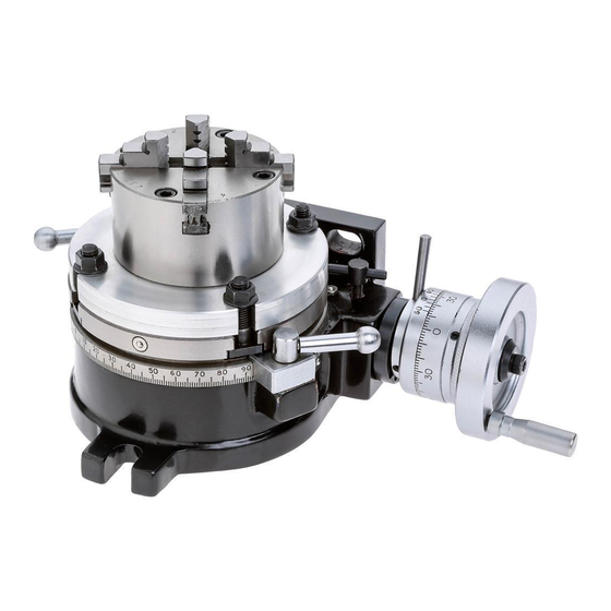
Scale Handwheel Scale Rotary Height Table Lock Adjustment T-Bolt Slot (1 of 2) Bolts Dead Center Figure 1. Model T25937 identification. To reduce your risk of serious injury, read this entire manual BEFORE using machine. Model T25937 (Mfd. Since 3/16) -
Page 6: Controls & Components
K. Dead Center Guide Screw: Prevents dead B. Vernier Scale: Has graduations that derive center from spinning inside tailstock. Also, helps secure adjustment knob setting. 20" (20 arc seconds). Model T25937 (Mfd. Since 3/16) -
Page 7: Section 1: Safety
Everyday ery. Never operate under the influence of drugs or eyeglasses are NOT approved safety glasses. alcohol, when tired, or when distracted. Model T25937 (Mfd. Since 3/16) - Page 8 EXPERIENCING DIFFICULTIES. If at any time debris. Make sure they are properly installed, you experience difficulties performing the intend- undamaged, and working correctly BEFORE ed operation, stop using the machine! Contact our operating machine. Technical Support at (570) 546-9663. Model T25937 (Mfd. Since 3/16)
-
Page 9: Section 2: Setup
Grizzly or the shipping agent. You MUST have the original pack- Box 1 (Figure 4): aging to file a freight claim. -
Page 10: Section 3: Operations
Tightening ects. Regardless of the content in this sec- the levers locks the table in place. tion, Grizzly Industrial will not be held liable for accidents caused by lack of training. To minimize finish problems associated with gear backlash when cutting circular slots, lightly tighten the lock levers to create extra drag. -
Page 11: Adjusting Handwheel Scale
Figure 9). The scale is attached to the backlash adjustment lever collar and is positioned accord- ing to the backlash setting. Vernier Scale Screw Figure 7. Location of collar set screw. Backlash Adjustment Lever Figure 9. Location of vernier scale. Model T25937 (Mfd. Since 3/16) -
Page 12: Mounting Rotary Table
T-slot, then install step clamp onto each Refer to your mill manual for this procedure. T-slot bolt (see Figure 10). The Model T25937 comes with (4) 80mm T-slot Install step blocks on milling table T-slots bolt assemblies, (2) step blocks, and (2) step (see Figure 10). - Page 13 Figure 10 for an example of this type of setup. efficiency, and general safety. The Model T25937 does not include fasteners to secure the rotary table to a milling table in the ver- tical position. The instructions below are included to provide an example of how the table can be mounted.
-
Page 14: Mounting Chuck On Rotary Table
Tighten all T-slot bolts completely, then Round check runout again. If necessary, repeat Stock Steps 2–6, then tighten hex huts. T-Bolt Figure 14. Magnetic base dial indicator placed next to rotary table. -12- Model T25937 (Mfd. Since 3/16) -
Page 15: Aligning Workpiece With Mill Spindle
Rotate mill spindle by hand in just one direc- rotated, then securely clamp workpiece to tion while watching indicator dial. T-slot table. Adjust mill table position until indicator dial reads zero deviation. -13- Model T25937 (Mfd. Since 3/16) -
Page 16: Aligning Table With Mill X-Axis
Move mill table in and out to indicate across full width of rotary table. If necessary, loosen clamps and lightly tap rotary table into position so indicator reads zero deviation across full width of rotary table, then reclamp it. -14- Model T25937 (Mfd. Since 3/16) -
Page 17: Adjusting Vernier Scale
If it is, rotate it counterclock- wise one full turn and “sneak” up on mark again. Once you are satisfied with table posi- tion, lock it in place with table locks. Continued on next page -15- Model T25937 (Mfd. Since 3/16) - Page 18 If it is, rotate it counterclock- wise one full turn and “sneak” up on the mark again. Once you are satisfied with the table position, lock it in place with the table locks. Figure 21. More vernier scale adjustments. -16- Model T25937 (Mfd. Since 3/16)
-
Page 19: Angular Indexing
This procedure eliminates errors due to backlash in worm gear. Sector Arm Figure 23. Installing dividing plate and placing sector arm assembly. -17- Model T25937 (Mfd. Since 3/16) -
Page 20: Simple Indexing
Simple indexing is used when milling multiple, even surfaces on a round workpiece. The Model T25937 has three dividing plates with the following hole circles: Plate: 15, 16, 17, 18, 19, 20. Plate: 21, 23, 27, 29, 31, 33. - Page 21 Pull back on crank handle spring-loaded pin to remove pin from dividing plate hole. Pull pin out far enough to clear tops of sector arms while you crank, so you won't bump sector arms and lose your position. -19- Model T25937 (Mfd. Since 3/16)
- Page 22 1 16/29 3 18/39 3 6/18 1 10/20 30/31 45/47 3 3/29 1 14/31 18/19 1 9/21 15/16 2 28/31 2 13/16 1 15/39 45/49 2 24/33 1 12/33 30/33 18/20 Figure 30. Index table. -20- Model T25937 (Mfd. Since 3/16)
-
Page 23: Mounting Tailstock
If there is an offset, adjust position of tailstock half the distance of the offset and The Model T25937 comes with a tailstock for recheck (see Figure 32). the rotary table. The tailstock supports larger... -
Page 24: Section 4: Accessories
Perfect serious personal injury or machine damage. for all setup and inspection work. To reduce this risk, only install accessories recommended for this machine by Grizzly. NOTICE Refer to our website or latest catalog for additional recommended accessories. - Page 25 These test indicators have an easy to read dial and a pivoting stylus that moves at right angles to the dial face. Figure 38. H2939 4-Pc. Edge Finder Set. Figure 40. Test Indicator. www.grizzly.com 1-800-523-4777 order online at or call -23- Model T25937 (Mfd. Since 3/16)
-
Page 26: Section 5: Maintenance
Lubrication To reduce risk of shock or accidental startup, always Ball Oilers disconnect machine from Oil Type ..Grizzly T23963 or ISO 32 Equivalent power before adjustments, Oil Amount ........1 or 2 Squirts maintenance, or service. Lubrication Frequency ......... Daily... -
Page 27: Section 6: Parts
SECTION 6: PARTS We do our best to stock replacement parts when possible, but we cannot guarantee that all parts shown are available for purchase. Call (800) 523-4777 or visit www.grizzly.com/parts to check for availability. Main Parts Breakdown -25- Model T25937 (Mfd. Since 3/16) - Page 28 Please Note: We do our best to stock replacement parts whenever possible, but we cannot guarantee that all parts shown here are available for purchase. Call (800) 523-4777 or visit our online parts store at www.grizzly.com to check for availability.
- Page 29 Would you recommend Grizzly Industrial to a friend? _____ Yes _____No Would you allow us to use your name as a reference for Grizzly customers in your area? Note: We never use names more than 3 times. _____ Yes _____No 10.
- Page 30 FOLD ALONG DOTTED LINE Place Stamp Here GRIZZLY INDUSTRIAL, INC. P.O. BOX 2069 BELLINGHAM, WA 98227-2069 FOLD ALONG DOTTED LINE Send a Grizzly Catalog to a friend: Name_______________________________ Street_______________________________ City______________State______Zip______ TAPE ALONG EDGES--PLEASE DO NOT STAPLE...
-
Page 31: Warranty & Returns
WARRANTY & RETURNS Grizzly Industrial, Inc. warrants every product it sells for a period of 1 year to the original purchaser from the date of purchase. This warranty does not apply to defects due directly or indirectly to misuse, abuse, negligence, accidents, repairs or alterations or lack of maintenance.