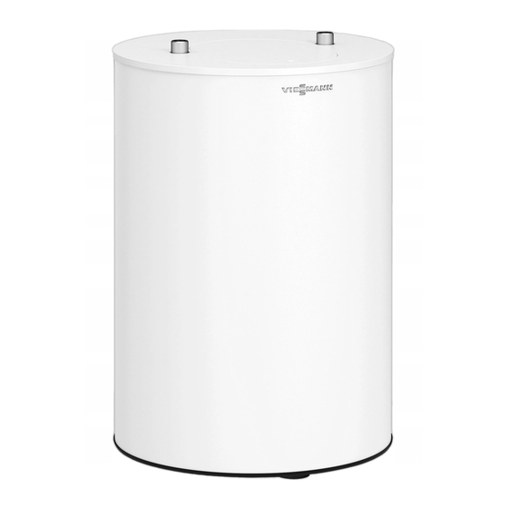
Viessmann Vitocell 100-W Installation And Service Instructions For Contractors
Dhw cylinder
Hide thumbs
Also See for Vitocell 100-W:
- Installation and service instructions for contractors (20 pages) ,
- Technical manual (56 pages) ,
- Installation and service instructions manual (36 pages)
Summary of Contents for Viessmann Vitocell 100-W
- Page 1 VIESMANN Installation and service instructions for contractors Vitocell 100-W Type CUGA DHW cylinder 100 l VITOCELL 100-W Please keep safe. 6150560 GB 1/2020...
- Page 2 Safety instructions Safety instructions Please follow these safety instruc- tions closely to prevent accidents and material losses. Safety instructions explained Danger Note This symbol warns against the risk Details identified by the word "Note" of injury. contain additional information. Please note This symbol warns against the risk of material losses and environmen- tal pollution.
- Page 3 Please note Repairing components that fulfil a safety function can compromise the safe operation of the system. Replace faulty components only with genuine Viessmann spare parts. Auxiliary components, spare and wearing parts Please note Spare and wearing parts that have...
-
Page 4: Table Of Contents
Index Index Information Disposal of packaging ................Symbols ....................Intended use ..................Product information ................Vitocell 100-W, type CUGA ..............■ Inspection and maintenance ..............System examples .................. Spare parts lists ..................Preparing for installation Unpacking the DHW cylinder .............. - Page 5 Information Disposal of packaging Please dispose of packaging waste in line with statu- tory regulations. Symbols The steps in connection with commissioning, inspec- Symbol Meaning tion and maintenance are found in the "Commission- Reference to other document containing ing, inspection and maintenance" section and identified further information as follows: Step in a diagram:...
- Page 6 Incorrect usage also occurs if the components in the system are modified from their intended use (e.g. through direct DHW heating in the collector). Product information Vitocell 100-W, type CUGA Enamelled DHW cylinder with internal indirect coil for ■ Capacity: 100 l DHW heating in conjunction with wall mounted boilers ■...
- Page 7 Preparing for installation Unpacking the DHW cylinder Fig. 1...
- Page 8 Preparing for installation Connections View from above Rear view FEDC Cylinder flow Sensor well for cylinder temperature controller Cylinder return Inspection and cleaning aperture DHW circulation Protective magnesium anode with earth cable Cold water Connection, temperature sensor for thermometer Siting information Please note Note The thermal insulation must not come into con-...
- Page 9 Installation sequence Cylinder temperature sensor, anode connection Fig. 3 Protective magnesium anode Earth cable 2. Route the sensor lead around the r.h. side past the 5. Insert the cylinder temperature sensor into the sen- cylinder return to the sensor well. sor well as far as it will go.
-
Page 10: Thermometer Sensor (If Supplied), Closing The Appliance
Installation sequence Thermometer sensor (if supplied), closing the appliance 1. Route the thermometer lead through the groove in the flange rim. 2. Insert the thermometer sensor as far as it will go into the clamping bracket. Installation instructions, casing for covering connecting leads/cables 6. -
Page 11: Safety Valve
Installation sequence Connections on the DHW side (cont.) Equip the DHW circulation pipe with a DHW circula- ■ Permissible temperature 95 °C tion pump, check valve and time switch. Permissible operating pressure 10 bar ■ Connect the DHW circulation pump to the boiler con- (1.0 MPa) trol unit or via the time switch. -
Page 12: Connecting The Equipotential Bonding
Installation sequence Connecting the equipotential bonding Connect the equipotential bonding in accordance with : Connect the equipotential bonding in accordance the requirements stipulated by your local power supply with the requirements stipulated by your local power utility and VDE [or local] regulations. supply utility and current SEV [or local] regulations. -
Page 13: Steps - Commissioning, Inspection And Maintenance
Commissioning, inspection, maintenance Steps - commissioning, inspection and maintenance Commissioning steps Inspection steps Maintenance steps Page • 1. Filling the DHW cylinder...................... 14 • • 2. Shutting down the system • • 3. Checking the safety valve function • • 4. - Page 14 Commissioning, inspection, maintenance Filling the DHW cylinder 1. Fill the DHW cylinder on the DHW side. 2. Check the fittings on the heating water and DHW sides for leaks and tighten if required. Note When the DHW cylinder is pressurised, tighten the 3.
- Page 15 Commissioning, inspection, maintenance Cleaning the inside of the DHW cylinder (cont.) 3. Disconnect the DHW cylinder from the pipework to prevent cleaning agents and contaminants from entering the pipework. 4. Remove loose deposits with a high pressure cleaner. Please note Pointed or sharp cleaning tools will damage the cylinder interior.
- Page 16 Commissioning, inspection, maintenance Returning the DHW cylinder to use 1. Reconnect the DHW cylinder to the pipework. 2. Insert new gasket underneath flange cover 3. Fit flange cover with earth cable Max. torque: 25 Nm 4. Push earth cable onto tab 5.
- Page 17 Commissioning/service reports Commissioning/service reports Commissioning Maintenance/service Maintenance/service Date: Maintenance/service Maintenance/service Maintenance/service Date: Maintenance/service Maintenance/service Maintenance/service Date: Maintenance/service Maintenance/service Maintenance/service Date: Maintenance/service Maintenance/service Maintenance/service Date:...
- Page 18 Specification Specification Product characteristics Standby heat loss kWh/24 h 1.24 Standard parameter to EN 12897:2016 Q at 45 K temp. differential...
-
Page 19: Final Decommissioning And Disposal
Disposal Final decommissioning and disposal Viessmann products can be recycled. Components For decommissioning the system, isolate the system and substances from the system are not part of ordi- from the power supply and allow components to cool nary household waste. -
Page 20: Declaration Of Conformity
Certificates Declaration of conformity We, Viessmann Werke GmbH & Co. KG, D-35107 Using the serial number, the full Declaration of Con- Allendorf, declare as sole responsible body that the formity can be found on the following website: named product complies with the European directives www.viessmann.co.uk/eu-conformity...


