Table of Contents
Advertisement
18-GF12D1-1A-EN
ALL phases of this installation must comply with NATIONAL, STATE AND LOCAL CODES
Important: This Document is customer property and is to remain with this unit.
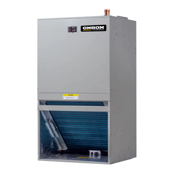
The JMM4A series wall mount air handler is designed for installation in a closet, utility room,
alcove and can be wall mounted. These versatile units are applicable to air conditioning
applications. Field installed electric resistance heaters are available.
All aluminum coil.
•
•
Factory installed piston style refrigerant control-
Field installed TXV kits available.
•
Blower and coil slide out easily for maintenance.
Factory-sealed cabinet certified to achieve 2% or
•
less air leakage rate at 1.0 inch water column.
Front or bottom return air.
•
•
Painted finish on galvanized steel.
•
Sturdy polycarbonate drain pans.
- Air handler has factory installed drain pan and
is shipped for upflow applications only.
208/230 VAC operation.
•
Stud or wall mount installation.
•
Fully insulated cabinet.
•
•
3/4'' NPT primary and secondary drains.
AHRI certified and ETL listed.
•
5, 7.5 and 10 kW SINGLE PHASE ELECTRIC
•
HEATERS
- Circuit breakers are standard on all single
phase 5, 7.5 and 10 kW heaters.
JMM4A0A18S21SAA
JMM4A0A24S21SAA
JMM4A0B30S21SAA
JMM4A0B36S31SAA
A
Advertisement
Table of Contents

Related Manuals for Trane OXBOX JMM4A0A18S21SAA


Summary of Contents for Trane OXBOX JMM4A0A18S21SAA
- Page 1 18-GF12D1-1A-EN JMM4A0A18S21SAA JMM4A0A24S21SAA JMM4A0B30S21SAA JMM4A0B36S31SAA ALL phases of this installation must comply with NATIONAL, STATE AND LOCAL CODES Important: This Document is customer property and is to remain with this unit. The JMM4A series wall mount air handler is designed for installation in a closet, utility room, alcove and can be wall mounted.
-
Page 2: Section 2. Safety Information
Section 2. Safety Information Note: The small air handlers have been evaluated in accordance WARNING with the Code of Federal Regulations, Chapter XX, Part 3280 or the equivalent. “SUITABLE FOR MOBILE HOME USE.” SAFETY HAZARD! This information is intended for use by individuals possessing adequate backgrounds of electrical and mechanical experience. - Page 3 CAUTION WARNING Make sure the blower motor support is tight CORROSION HAZARD! To prevent shortening its service life, (3-motor mount bolts) then check to see if the air handler should not be used during the finishing phases of construction. The low return air temperatures can lead to wheel is secured to motor shaft before operating unit.
-
Page 4: Section 3. Installation Instructions
Section 3. Installation Instructions WALL STRUTURE PROVIDED AIR HANDLER MOUNTING BRACKET 3.1 Unpacking Carefully unpack the unit and inspect the contents for damage. If any damage is found at the time of delivery, proper notification and claims should be made with the carrier. Check the rating plate to assure model number and voltage. - Page 5 3.3 Duct Work Field ductwork must comply with the National Fire Protection Association NFPA 90A, NFPA 90B and any applicable local ordinance. AIRFLOW WARNING Do not, under any circumstances, connect return ductwork to any other heat producing device such as fireplace insert, stove, etc. Unauthorized use of such devices may result in fire, carbon monoxide poisoning, explosion, personal injury or property damage.
-
Page 6: Power Wiring
3.5 Refrigerant Piping • Low voltage control connections are made to low voltage pigtails Refrigerant pipe connections are located on the top of the unit. extending from top of air handler (see Figure 1). Connections for Refrigerant piping external to the unit shall be sized in accordance control wiring are made with wire nuts. -
Page 7: Outdoor Unit
3.11 Sequence of Operation Note: Chart is based on 400 CFM/Ton indoor airflow and 50% relative humidity. If indoor relative humidity is above 70% or Cooling (cooling only) below 20%. use indoor wet bulb temperature only. Airflow range When the thermostat calls for cooling, the circuit from R to G is is 375 to 425 CFM/Ton. -
Page 8: Component Arrangement
CAUTION: SCHEMATIC DIAGRAM NOT SUITABLE FOR USE ON SYSTEMS EXCEEDING 150V TO GROUND ATTENTION: SEE RATING PLATE FOR VOLTS&HERTZ NE CONVIENT PAS AUXINSTALLATIONS DE PLUS DE 150V ALA TERRE COMPONENT ARRANGEMENT ELECTRIC HEAT WIRING CONNECTION (WHEN APPLIED) SEE NOTE 6 POWER DISC PLUG PLATE... - Page 9 Section 5. - Heater Pressure Drop Table - Use For All TMM4B Wall Mount Air Handler Models B A YHTRJ505BRKA* MODEL B A YHTRJ508BRKA* 1400 0.06 0.08 0.08 B A YHTRJ510BRKA* 1300 0.06 0.08 0.08 Accessory Heater Usage 1200 0.06 0.08 0.08 NUMBER...
-
Page 10: Dimensional Data
Section 7. Dimensional Data 6.1 UNIT DIMENSIONS Liquid line connection Low voltage copper (sweat)(3/8"dia pipe) connection Vapor line connection copper (sweat)(3/4"dia pipe) Breaker switch (for electric heater High voltage connection only) 7/8 " dia knock outs Front return shown. Units may also be installed as bottom return. -
Page 11: Dimension Data
Fig. -2 BACK DIMENSIONS DIMENSION DATA Dimension inch [mm] Model number JMM4A0A18S21SAA 24-9/10" [150] 10-1/8"[61] 119-1/20" [717] JMM4A0A24S21SAA 24-9/10" [150] 10-1/8"[61] 119-1/20" [717] JMM4A0B30S21SAA 24-9/10" [150] 10-1/8"[61] 132" [795] JMM4A0B36S31SAA 24-9/10" [150] 10-1/8"[61] 132" [795]... - Page 12 Twenty ThreeC,LLC Since the manufacturer has a policy of continuous product and 800 Beaty Street, product data improvement, it reserves the right to change the Davidson NC,28036 design and specification without notice. www.oxboxhvac.com © 2019TwentyThreeC, LLC For more information contact 16123000A19244 V2.0 your local dealer (distributor)