Endress+Hauser Solimotion FTR20 Operating Instructions Manual
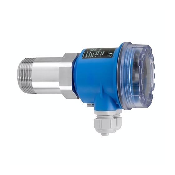
Flow indicator for bulk solids
Hide thumbs
Also See for Solimotion FTR20:
- Operating instructions manual (76 pages) ,
- Technical information (44 pages) ,
- Instructions manual (16 pages)

Related Manuals for Endress+Hauser Solimotion FTR20


Summary of Contents for Endress+Hauser Solimotion FTR20
- Page 1 Products Solutions Services BA001136F/97/EN/01.13 Operating Instructions Solimotion FTR20 Flow indicator for bulk solids...
-
Page 2: Table Of Contents
Requirements for the personnel ........6 Intended use ..............6 Appendix ..........50 Workplace safety ............6 Operational safety ............7 13.1 Settings of the Solimotion FTR20 ......50 Product safety ..............7 13.2 Declaration of Contamination ........ 51 Product description ........8 Index ..............Product structure ............8 Functional principle ............8... -
Page 3: Information On The Document
Solimotion FTR20 Information on the document Information on the document Document function These Operating Instructions contain all the information that is required in various phases of the life cycle of the device: from product identification, incoming acceptance and stor- age, to mounting, connection, operation and commissioning through to troubleshooting, maintenance and disposal. - Page 4 Information on the document Solimotion FTR20 1.2.3 Tool symbols Symbol Meaning Flat blade screwdriver Phillips head screwdriver Allen key Hexagon wrench 1.2.4 Symbols for information types Symbol Meaning Indicates additional information. Reference to documentation Refers to the corresponding device documentation.
-
Page 5: Documentation
The listed document types are available: • In the Download Area of the Endress+Hauser Internet site: www.endress.com → Download 1.3.2 Safety instructions (XA) Depending on the approval, safety instructions (XA) are included with the device;... -
Page 6: Basic Safety Instructions
The manufacturer is not liable for damage caused by improper or non-designated use. Verification for borderline cases: • F or special fluids and fluids for cleaning, Endress+Hauser is glad to provide assistance in verifying the corrosion resistance of fluid-wetted materials, but does not accept any warranty or liability. -
Page 7: Operational Safety
Conversions to the device Unauthorized modifications to the device are not permitted and can lead to unforeseeable dangers. • I f, despite this, modifications are required, consult with Endress+Hauser. Repair To ensure continued operational safety and reliability, • C arry out repairs on the device only if they are expressly permitted. -
Page 8: Product Description
4 Cable glands Functional principle The Solimotion FTR20 flow indicator for bulk solids works using microwave technology and detects the movement of bulk solids and changes in the mass flow of a solid flow. The device transmits a signal that is reflected by the moving bulk solids. In doing so, the FTR20 measures the strength of the reflected, frequency-shifted energy (Doppler effect) and uses it to form a display value or output signal. -
Page 9: Incoming Acceptance And Product Identification
Solimotion FTR20 Incoming acceptance and product identification Incoming acceptance and product identification Incoming acceptance • Check whether the package or contents are damaged. • C heck that the goods supplied are complete and compare the scope of delivery with your order details. - Page 10 Product description Solimotion FTR20 4.2.2 Identifying the device via the order code Approval: AA Non-hazardous area BA ATEX II 1/2D Ex ta/tb IIIC T102°C Da/Db IP66 ATEX II 2D Ex tb IIIC T102°C Db IP66 IECEx Ex ta/tb IIIC T102°C Da/Db IP66 IECEx Ex tb IIIC T102°C Db IP66...
-
Page 11: Transportation And Storage
Solimotion FTR20 Product description The overview of the order structure does not mark options which are mutually exclusive. Transportation and storage 4.3.1 Storage The device must be stored in a dry, clean area and protected against damage from impact (EN 837-2). Always store the device with the housing cover closed and the cable glands sealed off (to protect from dust). -
Page 12: Installation
Installation Mounting requirements The Solimotion FTR20 flow indicator for bulk solids comes with a standard thread (R 1½ as per EN 10226 or 1½ NPT as per ANSI/ASME B1.20.1) as a process connection. This enables easy installation in existing container couplings or nozzles. - Page 13 Solimotion FTR20 Installation • To maintain the maximum temperature of +70°C at the FTR20, we recommend a mini- mum difference (X) of 200 mm between the process or the insulation and the device. • The individual extensions can also be combined in any way desired.
-
Page 14: Installation Dimensions
ø 77 Mounting the Solimotion FTR20 The Solimotion FTR20 flow indicator for bulk solids comes with a standard thread (R 1½ as per EN 10226 or 1½ NPT as per ANSI/ASME B1.20.1) as a process connection. This enables easy installation in existing container couplings or nozzles. -
Page 15: Post-Mounting Check
Solimotion FTR20 Installation 55 mm 2.5 mm Screw in the FTR20 tightly Orient the electronics housing as desired (can be rotated by 360°) Fasten the electronics housing Post-mounting check Is the device undamaged (visual inspection)? Does the device conform to the measuring point specifications? For example: • Process temperature • Process pressure • Ambient temperature •... -
Page 16: Electrical Connection
• The maximum thermal load of the introduced cables and lines must be observed. • Endress+Hauser recommends commercially available installation wires with a maxi- mum connection cross-section of 1.5 mm In addition, always observe the safety instructions on this provided in Chapter 2 of these... - Page 17 Solimotion FTR20 Electrical connection For optimum electromagnetic compatibility, the potential matching line should be as short as possible. The recommended minimum cable cross-section is 2.5 mm The Solimotion’s potential matching should be included in the local potential matching. 6.2.2 Wiring of F15 housing (stainless steel) 0.6 x 3.5 mm...
- Page 18 Electrical connection Solimotion FTR20 6.2.2 Power supply connection Depending on the device version selected (see product identification), a power supply with the following values can be connected to the Solimotion: • 85 - 253 V (AC), 50/60 Hz, max. 4 VA •...
- Page 19 Solimotion FTR20 Electrical connection 6.2.3.1 Relay The following characteristic data apply for the relay signal output (floating switchover contact): • Switching capacity: - AC: 250 V / 6 A - DC: 125 V / 0.4 A or 30 V / 5 A •...
-
Page 20: Post-Connection Check
Electrical connection Solimotion FTR20 6.2.3.3 Current output The following characteristic data apply for the current output: • 4-20 mA, active • Max. load: 600 Ω Post-connection check Are the device and the connecting cable(s) undamaged (visual inspection)? Do the cables used comply with the requirements? ... -
Page 21: Operation Options
Solimotion FTR20 Operation options Operation options Overview The Solimotion is configured using a function selection switch (encoding switch) and two operating buttons (adjustment to the sensitivity needed for clear and unambiguous mate- rial flow detection of the products). The parameter configuration is stored internally and is retained even after the supply voltage is disconnected. - Page 22 Operation options Solimotion FTR20 7.1.1 Device-specific symbols Symbol Meaning LED on Indicates an illuminated LED LED off Indicates a non-illuminated LED Configuration mode Indicates the function number or value Normal operation Indicates only the signal strength of the bulk solids movement...
-
Page 23: Structure And Function Of The Control
Once parameter configuration is complete (i.e. once the flow indicator has been adapted to the bulk solids in question), the encoding switch must be returned to the “0” position. The Solimotion FTR20 is now ready for operation. Endress+Hauser... -
Page 24: Commissioning
You can write down all configurable settings of the following chapters in a table for docu- mentation purposes (→ 50). Calibrating the Solimotion The Solimotion FTR20 can be calibrated under the following conditions: Calibration in the process for moving bulk solids • Automatic calibration for moving bulk solids (Function 1, → 25), sufficient for most applications •... - Page 25 Move the encoding switch to the initial position 0 → Display of the current signal strength • The Solimotion FTR20 is calibrated if, - for moving bulk solids, the switch point (LED 5) of the switch output is exceeded reliably.
- Page 26 Move the encoding switch to the initial position 0 → Display of the current signal strength • The Solimotion FTR20 is calibrated if, - for moving bulk solids, the switch point (LED 5) of the switch output is exceeded reliably.
- Page 27 Introduction The Solimotion FTR20 detects the movement of a wide variety of bulk solids. The total detection range (0 to 100% minimum to maximum possible signal strength) is designed to be correspondingly wide. This way even products with very low reflection (small signal strengths), such as rigid polystyrene foam, can be detected.
- Page 28 Commissioning Solimotion FTR20 0% 100% a Illuminated LEDs of the signal strength display b Total available detection range The detection range is configured as follows: Move the encoding switch to position C → Display of the function number → After 2 seconds: Display of the configured detection range, example: Press the key on the device to increase or decrease the detection range depend- ing on the gain (→...
- Page 29 Solimotion FTR20 Commissioning Gain (function B) The configured detection range (function C) can be shifted within the maximum possible range using the gain. Depending on the detection range, it can be configured in the range from 1 to a maximum of 10 LEDs in 20 increments (2 increments correspond to 1 LED).
- Page 30 Commissioning Solimotion FTR20 The gain is configured as follows: Move the encoding switch to position B → Display of the function number → After 2 seconds: Display of the configured gain, example: Press the key on the device to increase or decrease the gain depending on the detection range (see the following table) →...
- Page 31 The bulk solids for which movement is to be detected are transported via a conveyor belt. Due to process fluctuations, the belt is loaded unevenly. FTR20 Default setting of the Solimotion FTR20 (→ 39): Gain (function B) Detection range (function C) Signal strength display in this particular example with the default settings: Maximum loading (current output: 15.2 mA)
- Page 32 Solimotion FTR20 Example: Calibrate switch output For example, the Solimotion FTR20 with switch output should be calibrated such that the output relay remains closed despite the fluctuating signal strength (if loading of the belt is low (= minimum signal strength), the switch point (LED 5) must remain reliably exceed- ed).
- Page 33 Commissioning Example: Calibrate current output For example, the Solimotion FTR20 with current output should be calibrated such that the irregular loading height can be detected due to process fluctuations (make better use of the output signal range (4-20 mA) in comparison to the default setting). The movement of the empty belt must not be detected.
-
Page 34: Advanced Settings
Commissioning Solimotion FTR20 Advanced settings The following settings are optional and not required in most cases; it may make sense to use them only for special adaptations to the application and/or to the downstream analy- sis (process control system). Overview of the factory defaults →39 8.3.1 Hysteresis (function 5) - Page 35 Solimotion FTR20 Commissioning 8.3.2 Limit signal function (function 6) For devices with a relay and solid-state relay, the limit signal function determines the switching behavior upon exceeding and undershooting the limit value (upper limit value LED 5, lower limit determined by hysteresis).
- Page 36 Commissioning Solimotion FTR20 8.3.3 Switching delay (function 7 and 8) An additional switch-on and/or off delay can be configured for the switch output. This can be used, for example, to stabilize the switch output when the signal strength fluctuates greatly, so that the relay does not switch until the switch point has been exceeded or un- dershot for a corresponding time.
- Page 37 Solimotion FTR20 Commissioning The switching delays t(S) and t(T) are configured as follows: Move the encoding switch to position 7 (switch-on delay t(S)) or position 8 (switch-off delay t(T)) → Display of the function number, switch-off delay example → After 2 seconds: Display of the configured delay time, example:...
- Page 38 Commissioning Solimotion FTR20 Possible settings: Setting Damping Setting Damping 100 ms 200 ms 300 ms 10 s 500 ms 20 s The damping is configured as follows: Move the encoding switch to position A → Display of the function number →...
- Page 39 Solimotion FTR20 Commissioning 8.3.5 Resetting to factory defaults (function F) You can reset the Solimotion FTR20 to its factory defaults with this function as follows: Move the encoding switch to position F → Display of the function number → All LEDs go out after 2 seconds.
-
Page 40: Simulation
Commissioning Solimotion FTR20 Simulation The Solimotion FTR20 gives you the ability to simulate a signal and thereby an output variable, independent of the process, for example, in order to configure a downstream PLC or a data logger. The simulation is carried out as follows: Move the encoding switch to position 9 →... -
Page 41: Diagnostics And Troubleshooting
Solimotion FTR20 Diagnostics and troubleshooting Diagnostics and troubleshooting General troubleshooting Make sure beforehand that the following checks have been carried out: • “Post-mounting check” checklist (→ 15) • “Post-connection check” checklist (→ 20) Diagnostic information Error Possible cause Remedy Green LED not lit... -
Page 42: Maintenance
Maintenance Solimotion FTR20 Maintenance No special maintenance work is required. If medium is building up, however, we recommend regularly checking the beam path and cleaning where appropriate. This can be done using: • PTFE or ceramic disk at the process connection •... -
Page 43: Repair
• Carry out repairs according to the instructions. Following a repair, the individual testing prescribed for the device must be carried out. • A certified device may be converted to another certified version by Endress+Hauser Service only. • All repairs and modifications must be documented. -
Page 44: Spare Parts
Repair Solimotion FTR20 11.2 Spare parts Electronic inserts are available for all device versions of the FTR20. Specifications for the electronics you need are located on the nameplate. • All spare parts for the device, including the order code, are listed and can be ordered at the Internet site www.endress.com/deviceviewer (W@M Device Viewer). -
Page 45: Return
The device has to be returned in the event of repair, incorrect delivery or incorrect order- ing. As an ISO certified company and due to legal regulations, Endress+Hauser is obligated to use particular handling techniques for all returned products that have come into con- tact with a medium. -
Page 46: Accessories
Accessories Solimotion FTR20 Accessories All available accessories aid the installation of the Solimotion FTR20 in the process. Accessories Description Mounting bracket M6 / ¼" UNC Mounting bracket for frame mounting • Aluminum material: Part number 52017501 • Plastic material: Part number 52017502 The FTR20 can be easily mounted on an existing frame using a mounting bracket. - Page 47 Solimotion FTR20 Accessories Accessories Description Installation flange, as per ANSI/ASME B16.5 1½" 150 lbs 98.6 15.7 17.5 2" 150 lbs 120.7 152.4 19.1 19.1 4" 150 lbs 190.5 228.6 19.1 23.9 Connection dimensions as per ANSI/ASME B16.5, with 1½ NPT internal thread, material 316Ti (stainless steel): •...
- Page 48 Accessories Solimotion FTR20 Accessories Description Sight glass fitting, for unpressurized containers DN50 100 140 120 102 DN80 100 125 165 145 127 DN100 125 150 190 170 152 Weld-in fitting for unpressurized containers, materials: stainless steel 316Ti and silicone, Tmax = 200°C, borosilicate glass, screw-on installation •...
- Page 49 Solimotion FTR20 Accessories Accessories Description Sight glass fitting, acc. to DIN 28121 *1 - Seal, product-side DN50 165 125 DN80 200 160 DN100 100 125 235 190 Flange fitting acc. to DIN 28121 for screwing onto existing counter- flanges, materials: stainless steel 316Ti, PTFE and C4400, Pmax = 2.5 MPa (25 bar), Tmax = 200°C, borosilicate glass...
-
Page 50: Appendix
Appendix Solimotion FTR20 Appendix 13.1 Settings of the Solimotion FTR20 You can make a note of your settings for documentation purposes using the following table: Order code: FTR20 - Instrument number: Function/meaning Value range Setting Hysteresis ( Minimum) ··· ( Maximum) -
Page 51: Declaration Of Contamination
Erklärung zur Kontamination und Reinigung Please reference the Return Authorization Number (RA#), obtained from Endress+Hauser, on all paperwork and mark the RA# clearly on the outside of the box. If this procedure is not followed, it may result in the refusal of the package at our facility. - Page 52 Solimotion FTR20 Endress+Hauser...
- Page 53 Solimotion FTR20 Endress+Hauser...
- Page 54 Solimotion FTR20 Endress+Hauser...
- Page 55 Solimotion FTR20 Index Index Accessories ..............46 Operating buttons ............. 21 Adjustment ..............24 Order code ..............10 Orientation ............12 Cable gland ..............16 Commissioning ............24 Potential matching ............ 16 Control ................ 21 Power supply .............. 18 Current output ........... 20 Power switch ..............
- Page 56 71205221 www.addresses.endress.com...