Advertisement
Quick Links
IT
PANNELLO DI COMANDO REMOTO PER VENTILCONVETTORE TER-N
EN
REMOTE CONTROL PANEL FOR CONVECTOR FANS TER-N
FR
PANNEAU DE COMMANDE À DISTANCE POUR VENTILO-CONVECTEURS TER-N
ES
PANEL DE MANDO REMOTO PARA VENTILOCONVECTOR TER-N
PT
PAINEL DE COMANDO REMOTO PARA VENTILO-CONVETOR TER-N
Premessa:
Ogni termostato può controllare un solo ventilconvettore:
Il kit è composto da:
•
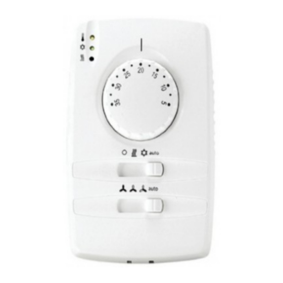
n° 1 termostato (Fig.1)
•
n° 2 viti testa cilindrica intaglio a croce ø3.5x16 mm.
•
n° 1 sonda acqua
•
n° 2 passacavi "DG11"
•
n° 1 istruzione di montaggio
DICHIARAZIONE DI CONFORMITÀ
Il prodotto è conforme alle direttive CEE seguenti:
•
73/23/CEE e successive modificazioni in conformità
alle seguenti norme:
•
EN 60730-2-9
•
89/336/CEE e successive modificazioni e rispetta le
seguenti norme:
•
EN 60730-2-9
•
Emissioni: EN 55014-1
•
Immunità: EN 55014-2
USI CONSENTITI
Per ragioni di sicurezza l'apparecchio deve essere
utilizzato secondo le istruzioni fornite dal costruttore
e in particolare, in condizioni normali di utilizzo non si
deve accedere alle parti sotto tensioni e/o riscaldanti
per i pericoli che ne derivano. Inoltre l'apparecchio deve
essere protetto dall'acqua e dalla polvere.
USO NON CONSENTITO
Qualsiasi uso diverso da quello consentito è vietato.
Si fa presente che i contatti relè forniti sono di tipo
funzionale e sono soggetti a guasto: eventuali dispositivi
di protezione previsti dalla normativa di prodotto o suggeriti dal buon senso in ordine a
palesi esigenze di sicurezza devono essere realizzati al di fuori dello strumento.
DATI TECNICI
Tensione di alimentazione: 230V~ ±10%
Frequenza di alimentazione: 50/60 Hz
Potenza massima assorbita: 12W
Corrente ammessa massima sui contatti: 1A max (230V~ FAN TRIAC) 0.5 max (230V~
VALVE TRIAC)
Classe di isolamento: II
Grado di protezione: IP30
Temperatura di funzionamento: 0÷55 °C
Umidità funzionamento. (non condensante): 10÷90% RH
Temperatura di immagazzinamento: -20÷85 °C
Umidità di immagazzinamento. (non condensante): 10÷90% RH
Contenitore: resina plastica PC+ABS
Dimensioni mm (Lxlxh): 120x80x40
Montaggio: a muro utilizzando il fondello come dima di foratura
INSTALLAZIONE
Aprire l'apparecchio con l'ausilio di un cacciavite a taglio, agendo
nelle fessure predisposte (A, B, C, D) vedi fig.2.
Appoggiare il dorso dell'apparecchio contro il muro e quindi
segnare i 4 fori da fare per il suo fissaggioutilizzando il fondello.
Individuare quindi le 2 morsettiere (fig. 3, morsettiera A e B).
Italiano
Cod. 3QE46020 - Rev. 00 - 11/2020
PREAMBLE
Each panel can control one single convector fan:
The kit is composed of:
- n° 1 thermostat (Fig.1)
- n° 2 screws, cylindrical head, ø3.5x16 mm
- n° 1 water probe
- n° 2 "DG11" core hitches
- n° 1 assembly instructions.
Fig. 1
exposed to potential faults. Therefore,
all protection devices required to comply with the product requirements and to ensure the
necessary level of safety must be installed externally.
TECHNICAL DATA
Supply voltage: 230V~ ±10%
Power frequency: 50/60 Hz
Maximum input power: 12W
Maximum admissible current on contacts: 1A max (230V~ FAN TRIAC) 0.5 max (230V~
VALVE TRIAC)
Insulation class: II
Protection class: IP30
Operating temperature: 0÷55 °C
Operating humidity (non-condensing): 10÷90% RH
Storage temperature: -20÷85 °C
Storage humidity (non-condensing): 10÷90% RH
Casing: plastic resin PC+ABS
Dimensions mm (Lxwxh): 120x80x40
Installation: wall-mounted using the rear hood as a drilling template
INSTALLATION
Open the device by applying a straight-bit screwdriver to the slots provided
(A, B, C and D), as shown in Fig.2.
Fig. 2
Place the rear of the device against the wall and mark the 4 holes for wall
mounting with a template. Locate the 2 terminal strips (Fig. 3, terminal
strips A and B).
Fig. 3
English
DECLARATION OF COMPLIANCE
This device complies with the following EC Directives and
standards:
-73/23/EEC and subsequent amendments, in compliance with
the following standards:
- EN 60730-2-9
- 89/336/EEC and subsequent amendments
- EN 60730-2-9
- Emissions: EN 55014-1
- Immunity: EN 55014-2
ORDINARY USE
For safety reasons, the device should always be used in
accordance with the manufacturer's instructions.
Access to live and/or heating parts should be avoided during
ordinary operation due to the hazards
entailed. The device should always be protected from water
and dust.
RESTRICTIONS
Uses other than those described above are forbidden. It is
useful to remember that the relay contacts
supplied with the device are functional contacts and therefore
1
Advertisement

Related Manuals for Ferroli Jolly Top 3V


Summary of Contents for Ferroli Jolly Top 3V
- Page 1 PANNELLO DI COMANDO REMOTO PER VENTILCONVETTORE TER-N REMOTE CONTROL PANEL FOR CONVECTOR FANS TER-N PANNEAU DE COMMANDE À DISTANCE POUR VENTILO-CONVECTEURS TER-N PANEL DE MANDO REMOTO PARA VENTILOCONVECTOR TER-N PAINEL DE COMANDO REMOTO PARA VENTILO-CONVETOR TER-N Italiano English PREAMBLE Premessa: Each panel can control one single convector fan: Ogni termostato può...
-
Page 2: Installation
Français Español AVANT-PROPOS INTRODUCCIÓN Chaque panneau permet de commander un seul ventilo-convecteur : Cada panel puede controlar un solo ventiloconvector: Le kit contient : El kit se compone de: - 1 thermostat (Fig.1) - n° 1 termostato (Fig.1) - 2 vis à tête cylindrique, ø3,5x16 mm - n°... - Page 3 Português PREÂMBULO Cada painel pode controlar um único ventilo-convetor: O kit é composto por: - n° 1 termostato (Fig.1) - n° 2 parafusos de cabeça cilíndrica ø3,5x16 mm - n° 1 sonda de água - n° 2 passa-cabos “DG11” - n° 1 instruções de montagem. DECLARAÇÃO DE CONFORMIDADE Este aparelho cumpre com as diretivas e normas UE seguintes: -73/23/EEC e posteriores alterações em conformidade com as normas seguintes:...
- Page 4 English Italiano COLLEGAMENTI CONNECTIONS Lo strumento è dotato di morsettiere a vite per il collegamento di cavi elettrici con sezione The device comes with screw terminal strips for the connection of leads with a maximum max. 1.5 mm (relativamente ai contatti di potenza, un solo conduttore per morsetto). cross-section of 1.5 mm2 (for power contacts;...
- Page 5 Fig. 4 230Vac-50Hz FAN COIL LOW COM • Le linee trateggiate indicano collegamenti a cura dell’installatore, filo tipo H05 VV-K 1.5 mmq o secondo installazione vedere normative specifiche. • The dotted lines indicate connections at installer’s charge cable H05 VV-K 1.5 mmq, consult the specific regulation. •...
- Page 6 English Italiano COLLEGAMENTO AL VENTILCONVETTORE CONNECTION TO FAN COIL 1 - Se presente togliere il mantello di copertura del ventilconvettore (vedi manuale di installazioe 1 - If present, remove the cover from the fan coil unit (see the fan coil installation and use manual). e uso del ventilconvettore).
- Page 7 SEGNALAZIONI Tutte le segnalazioni avvengono tramite tre leds poste sul frontale, in alto a sinistra. SIGNALS All signals are managed through the three LEDs located in the upper left section of the front part of the device. SIGNAUX Tous les signaux sont envoyés par l’intermédiaire de trois LEDs situées à l’avant du dispositif, en haut à gauche. SEÑALES Las señales se manifiestan mediante tres testigos ubicados en el frontal, en la parte superior izquierda.
- Page 8 English Italiano SONDE SENSORS SA int.: Sonda per temperatura ambiente (sempre presente internamente). SA int.: sensor for ambient air temperature (always built-in) Sensore montato a bordo scheda, nelle installazioni a muro. This sensor is fitted on the side of the card on wall-mounted devices. Campo di misura: -50…110 ºC.
- Page 9 CONFIGURAZIONE DIP SWITCHES Localizzare i dip switches sul dorso della scheda (vedi fig.8posizione C) e quindi configurare il sistema secondo le esigenze. CONFIGURATION OF DIP SWITCHES Locate the dip switches on the rear of the card (see Fig. 8 position C), then configure the system according to needs. RÉGLAGE DES COMMUTATEURS DIP Repérer les commutateurs dip au dos de la carte (voir Fig.8 position C) puis configurer ensuite le système selon vos besoins.
- Page 10 Ferroli spa ¬ 37047 San Bonifacio (Verona) Italy ¬ Via Ritonda 78/A tel. +39.045.6139411 ¬ fax +39.045.6100933 ¬ www.ferroli.com Made in Italy Cod. 3QE46020 - Rev. 00 - 11/2020...