Panasonic S-15MY2E5A Technical Data Manual
Vrf systems indoor unit
Hide thumbs
Also See for S-15MY2E5A:
- Technical data manual (44 pages) ,
- Installation instructions manual (20 pages) ,
- Operating instructions manual (180 pages)
Table of Contents
Advertisement
4-Way Cassette
(Type U1)
Indoor Unit
Class
15
22
4-Way Cassette
S-22MU1E5A
U1
4-Way Cassette
Y2
S-15MY2E5A
S-22MY2E5A
60×60
Low Silhouette
S-15MF2E5A
S-22MF2E5A
F2
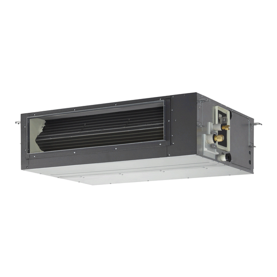
Ducted
Ceiling
T2
Wall Mounted
S-15MK2E5A
S-22MK2E5A
K2
Wall Mounted
K1
Slim Low Static
S-15MM1E5A
S-22MM1E5A
M1
Ducted
Indoor Unit
Class
180
224
High Static
S-180ME2E5
S-224ME2E5
E2
Pressure Ducted
85464869272003
VRF SYSTEMS INDOOR UNIT
28
36
S-28MU1E5A
S-36MU1E5A
S-45MU1E5A
S-28MY2E5A
S-36MY2E5A
S-45MY2E5A
S-28MF2E5A
S-36MF2E5A
S-45MF2E5A
S-36MT2E5A
S-45MT2E5A
S-28MK2E5A
S-36MK2E5A
S-45MK1E5A
S-28MM1E5A S-36MM1E5A
S-45MM1E5A S-56MM1E5A
280
S-280ME2E5
Ceiling
(Type T2)
45
56
60
S-56MU1E5A
S-60MU1E5A
S-73MU1E5A
S-56MY2E5A
S-56MF2E5A
S-60MF2E5A
S-73MF2E5A
S-56MT2E5A
S-73MT2E5A
S-56MK1E5A
S-73MK1E5A
Order No. SBPAC1403010CE
Low Silhouette Ducted
(Type F2)
73
90
106
S-90MU1E5A
S-106MU1E5A
S-140MU1E5A
S-90MF2E5A
S-106MF2E5A
S-140MF2E5A
S-106MT2E5A
S-140MT2E5A
S-106MK1E5A
TD831172-03
REFERENCE NO.
140
160
S-160MU1E5A
S-160MF2E5A
Advertisement
Table of Contents

Related Manuals for Panasonic S-15MY2E5A


Summary of Contents for Panasonic S-15MY2E5A
- Page 1 (Type T2) (Type F2) Indoor Unit Class 4-Way Cassette S-22MU1E5A S-28MU1E5A S-36MU1E5A S-45MU1E5A S-56MU1E5A S-60MU1E5A S-73MU1E5A S-90MU1E5A S-106MU1E5A S-140MU1E5A S-160MU1E5A 4-Way Cassette S-15MY2E5A S-22MY2E5A S-28MY2E5A S-36MY2E5A S-45MY2E5A S-56MY2E5A 60×60 Low Silhouette S-15MF2E5A S-22MF2E5A S-28MF2E5A S-36MF2E5A S-45MF2E5A S-56MF2E5A S-60MF2E5A S-73MF2E5A S-90MF2E5A...
-
Page 2: Table Of Contents
Design of VRF SYSTEM Design of VRF SYSTEMS Contents Contents 2. DESIGN OF VRF SYSTEMS 1. Electrical Wiring ........................1-1. General Precautions on Wiring ..................1-2. Recommended Wire Length and Wire Diameter for Power Supply System ....1-3. Wiring System Diagrams ....................2. -
Page 3: Design Of Vrf Systems
Design of VRF SYSTEMS Design of VRF SYSTEMS 1. Electrical Wiring 1. Electrical Wiring 1-1. General Precautions on Wiring (5) Do not allow wiring to touch the refrigerant tubing, (1) Before wiring, confirm the rated voltage of the unit as shown on its nameplate, then carry out the wiring closely compressor, or any moving parts of the fan. -
Page 4: Wiring System Diagrams
Design of VRF SYSTEMS Design of VRF SYSTEMS 1. Electrical Wiring 1. Electrical Wiring 1-3. Wiring System Diagrams Indoor unit (No. 1) Outdoor unit Power supply 220/230/240V ~50/60Hz Ground Remote To outdoor unit controller Ground Ground Indoor unit (No. 2) Power supply Ground 6P terminal board... - Page 5 Design of VRF SYSTEMS Design of VRF SYSTEMS 1. Electrical Wiring 1. Electrical Wiring CAUTION When linking the outdoor units in a network, disconnect the terminal extended from the short plug from all outdoor units except any one of the outdoor units. (When shipping: In shorted condition.) For a system without link (no wiring connection between outdoor units), do not remove the short plug.
- Page 6 Design of VRF SYSTEMS 1. Electrical Wiring (5) Use shielded wires for inter-unit control wiring (C) and Shielded wire ground the shield on both sides, otherwise misoperation from noise may occur. (Fig. 2-5) Connect wiring as shown in Section “1-3. Wiring System Ground Ground Fig.
- Page 7 Design of VRF SYSTEMS Design of VRF SYSTEMS 1. Electrical Wiring 1. Electrical Wiring Wiring sample Type E2 When connecting with 2WAY VRF system outdoor unit Use this screw when connecting the shield for the Inter-unit control wiring to ground. Functional ground screw (Schedule Timer) Remote Control Wiring...
-
Page 8: Selecting The Installation Site
Design of VRF SYSTEM Design of VRF SYSTEMS 2. SELECTING THE INSTALLATION SITE 2. SELECTING THE INSTALLATION SITE 2-7. High Static Pressure Ducted (Type E2) AVOID: areas where leakage of flammable gas may be expected. places where large amounts of oil mist exist. direct sunlight. -
Page 9: How To Install The Indoor Unit
Design of VRF SYSTEMS Design of VRF SYSTEMS 3. How to install the indoor unit 3. How to install the indoor unit 3-7 High Static Pressure Ducted (Type E2) 3-7-1. Required Minimum Space for Installation and Service (1) Dimensions of suspension bolt pitch and unit Unit: mm 1170 (Suspension bolt pitch) - Page 10 Design of VRF SYSTEMS Design of VRF SYSTEMS 3. How to install the indoor unit 3. How to install the indoor unit 3-7-2. Suspending the Indoor Unit Depending on the ceiling type: 1. Check the suspension bolt pitch. 2. Ensure that the ceiling is strong enough to support the weight of the unit. 3.
- Page 11 Design of VRF SYSTEMS Design of VRF SYSTEMS 3. How to install the indoor unit 3. How to install the indoor unit 3-7-3. Installing the Refrigerant Tubing The size of the refrigerant tubing is as shown in the table below. Table 2-10 Type ø19.05...
- Page 12 Design of VRF SYSTEMS Design of VRF SYSTEMS 3. How to install the indoor unit 3. How to install the indoor unit 3-7-4. Installing the Drain Piping (1) Prepare standard hard PVC pipe (O.D. 32 mm) Downward slant Sealing tape for the drain and use the supplied drain socket to prevent water leaks.
-
Page 13: Optional Parts
Design of VRF SYSTEMS Design of VRF SYSTEMS 4. Optional Parts 4. Optional Parts High Static Pressure Ducted (Type E2) Power cable NOTE Bundle the surplus power cable and signal output cable using the cable tie attached to the kit of the optional part CZ-CAPE2. 3WAY2 Power 3WAY1... - Page 14 VRF SYSTEMS Indoor Unit Specifications VRF SYSTEMS Indoor Unit Specifications 7. High Static Pressure Ducted Type (Type E2) 7. High Static Pressure Ducted Type (Type E2) Unit specifications (B) INDOOR MODEL S-224ME2E5 PANEL MODEL PERFORMANCE TEST CONDITION ISO15042 / AS / NZS3823.1 / EN14511 / EN12102 ø,Hz 1ø...
- Page 15 VRF SYSTEMS Indoor Unit Specifications VRF SYSTEMS Indoor Unit Specifications 7. High Static Pressure Ducted Type (Type E2) 7. High Static Pressure Ducted Type (Type E2) Unit specifications (C) INDOOR MODEL S-280ME2E5 PANEL MODEL PERFORMANCE TEST CONDITION ISO15042 / AS / NZS3823.1 / EN14511 / EN12102 ø,Hz 1ø...
- Page 16 VRF SYSTEMS Indoor Unit Specifications VRF SYSTEMS Indoor Unit Specifications 7. High Static Pressure Ducted Type (Type E2) 7. High Static Pressure Ducted Type (Type E2) Unit specifications (In case of Fresh Air Intake Mode) (D) INDOOR MODEL S-224ME2E5 PANEL MODEL PERFORMANCE TEST CONDITION *3 ø,Hz...
- Page 17 VRF SYSTEMS Indoor Unit Specifications VRF SYSTEMS Indoor Unit Specifications 7. High Static Pressure Ducted Type (Type E2) 7. High Static Pressure Ducted Type (Type E2) Unit specifications (In case of Fresh Air Intake Mode) (E) INDOOR MODEL S-280ME2E5 PANEL MODEL PERFORMANCE TEST CONDITION *3 ø,Hz...
- Page 18 VRF SYSTEMS Indoor Unit Specifications VRF SYSTEMS Indoor Unit Specifications 7. High Static Pressure Ducted Type (Type 7. High Static Pressure Ducted Type (Type E2) Indoor unit (B) MODEL No. S-224ME2E5 50Hz 〜220 - 230 - 240 V, single-phase Power source 60Hz 〜220 - 230 V, single-phase Controller P.C.B.
- Page 19 VRF SYSTEMS Indoor Unit Specifications VRF SYSTEMS Indoor Unit Specifications 7. High Static Pressure Ducted Type (Type 7. High Static Pressure Ducted Type (Type E2) Indoor unit (C) MODEL No. S-280ME2E5 50Hz 〜220 - 230 - 240 V, single-phase Power source 60Hz 〜220 - 230 V, single-phase Controller P.C.B.
- Page 20 VRF SYSTEMS Indoor Unit Specifications VRF SYSTEMS Indoor Unit Specifications 7. High Static Pressure Ducted Type (Type E2) 7. High Static Pressure Ducted Type (Type E2) 7-3. Dimensional Data Indoor unit: S-180ME2E5 / 224ME2E5 / 280ME2E5 Unit : mm Refrigerant liquid tubing (Flare) ø9.52 mm Type 180 Refrigerant gas tubing (Brazing) ø19.05 mm Type 224...
- Page 21 VRF SYSTEMS Indoor Unit Specifications VRF SYSTEMS Indoor Unit Specifications 7. High Static Pressure Ducted Type (Type E2) 7. High Static Pressure Ducted Type (Type E2) 7-4. Noise Criterion Curves MODEL : S-180ME2E5 SOUND LEVEL : HIGH 44 dB(A),LOW 40 dB(A) CONDITION : Under the unit 1.5 m SOURCE...
- Page 22 VRF SYSTEMS Indoor Unit Specifications VRF SYSTEMS Indoor Unit Specifications 7. High Static Pressure Ducted Type (Type E2) 7. High Static Pressure Ducted Type (Type E2) In the case of Fresh Air Intake Mode MODEL : S-224ME2E5 MODEL : S-280ME2E5 SOUND LEVEL : HIGH 43 dB(A) SOUND LEVEL...
-
Page 23: Distribution Joint Kits (Cz-P160Bk2, P680Bk2, P1350Bk2, P680Pj2, P1350Pj2, P4Hpc2, P4Hp2C2, P4Hp1C2)
VRF SYSTEMS Indoor Unit Specifications VRF SYSTEMS Indoor Unit Specifications 7. High Static Pressure Ducted Type (Type E2) 7. High Static Pressure Ducted Type (Type E2) 7-5. R.A.P. (Refrigerant Accumulation Protector) Value Kit Fresh Air Intake Mode Type of Outdoor Unit Parts Not In Use In Use... - Page 24 VRF SYSTEMS Indoor Unit Specifications VRF SYSTEMS Indoor Unit Specifications 7. High Static Pressure Ducted Type (Type E2) 7. High Static Pressure Ducted Type (Type E2) 7-6. Indoor Fan Performance Type 180 (Pa) Cooling Heating Item code Cooling Setting at “...
- Page 25 VRF SYSTEMS Indoor Unit Specifications VRF SYSTEMS Indoor Unit Specifications 7. High Static Pressure Ducted Type (Type E2) 7. High Static Pressure Ducted Type (Type E2) 7-7. External Static Pressure Setting Choose one of the methods (selection of “a”, “b”, “c” within the range of dotted line as shown in the flowchart below) and make settings.
- Page 26 VRF SYSTEMS Indoor Unit Specifications VRF SYSTEMS Indoor Unit Specifications 7. High Static Pressure Ducted Type (Type E2) 7. High Static Pressure Ducted Type (Type E2) 7-7-1. Indoor Fan Performance 1. Turn off the power breaker to halt the supply of electricity to the PC board. 2.
- Page 27 VRF SYSTEMS Indoor Unit Specifications VRF SYSTEMS Indoor Unit Specifications 7. High Static Pressure Ducted Type (Type E2) 7. High Static Pressure Ducted Type (Type E2) 7-7-3. Operating the High-spec Wired Remote Detailed settings 20:30 (THU) Controller (CZ-RTC3) Unit no. Code no.
- Page 28 VRF SYSTEMS Indoor Unit Specifications VRF SYSTEMS Indoor Unit Specifications 7. High Static Pressure Ducted Type (Type E2) 7. High Static Pressure Ducted Type (Type E2) 7-7-4. Operating the Timer Remote Controller (CZ-RTC4) How to set the external static pressure Table 4-8 Setting the external static pressure 1.
- Page 29 73MU1E5A / 90MU1E5A / 106MU1E5A / 140MU1E5A / 160MU1E5A 2. 4-Way Cassette 60×60 ......................6-3 S-15MY2E5A / 22MY2E5A / 28MY2E5A / 36MY2E5A / 45MY2E5A / 56MY2E5A 3. Low Silhouette Ducted ....................... 6-4 S-15MF2E5A / 22MF2E5A / 28MF2E5A / 36MF2E5A / 45MF2E5A / 56MF2E5A / 60MF2E5A / 73MF2E5A / 90MF2E5A / 106MF2E5A / 140MF2E5A / 160MF2E5A 4.
- Page 30 Electrical Data Electrical Data 6. High Static Pressure Ducted 6. High Static Pressure Ducted (1) Electric Wiring Diagram S-180ME2E5 / 224ME2E5 / 280ME2E5...
- Page 31 Capacity Table 1. Cooling Capacity of Indoor Unit For 2WAY VRF SYSTEM S-224ME2E5 Power supply :220/230/240V 1phase-50Hz , 220/230V 1phase-60Hz TC : Total Cooling Capacity (kW), SHC : Sensible Heat Capacity (kW) This data is when the indoor unit connects with 16HP outdoor unit. RATING CAPACITY: 22.4 kW AIR FLOW RATE : 56.0 m...
- Page 32 Capacity Table 1. Cooling Capacity of Indoor Unit For 2WAY VRF SYSTEM S-280ME2E5 Power supply :220/230/240V 1phase-50Hz , 220/230V 1phase-60Hz TC : Total Cooling Capacity (kW), SHC : Sensible Heat Capacity (kW) This data is when the indoor unit connects with 16HP outdoor unit. RATING CAPACITY: 28.0 kW AIR FLOW RATE : 72.0 m...
- Page 33 Capacity Table Capacity Table 1. Cooling Capacity of Indoor Unit 1. Cooling Capacity of Indoor Unit For 2WAY VRF SYSTEM For 2WAY VRF SYSTEM S-224ME2E5 Fresh Air Intake Mode Power supply : 220/230/240V 1phase-50Hz , 220/230V 1phase-60Hz TC : Total Cooling Capacity (kW), SHC : Sensible Heat Capacity (kW) This data is when the indoor unit connects with 16HP outdoor unit.
- Page 34 Capacity Table 2. Cooling Capacity of Indoor Unit For 3WAY VRF SYSTEM S-224ME2E5 Power supply :220/230/240V 1phase-50Hz , 220/230V 1phase-60Hz TC : Total Cooling Capacity (kW) SHC : Sensible Heat Capacity (kW) This data is when the indoor unit connects with 14HP outdoor unit. RATING CAPACITY: 22.4 kW AIR FLOW RATE : 56.0 m...
- Page 35 Capacity Table 2. Cooling Capacity of Indoor Unit For 3WAY VRF SYSTEM S-280ME2E5 Power supply :220/230/240V 1phase-50Hz , 220/230V 1phase-60Hz TC : Total Cooling Capacity (kW) SHC : Sensible Heat Capacity (kW) This data is when the indoor unit connects with 14HP outdoor unit. RATING CAPACITY: 28.0 kW AIR FLOW RATE : 72.0 m...
- Page 36 Capacity Table Capacity Table 2. Cooling Capacity of Indoor Unit 1. Cooling Capacity of Indoor Unit For 3WAY VRF SYSTEM For 3WAY VRF SYSTEM S-224ME2E5 Fresh Air Intake Mode Power supply : 220/230/240V 1phase-50Hz , 220/230V 1phase-60Hz TC : Total Cooling Capacity (kW), SHC : Sensible Heat Capacity (kW) This data is when the indoor unit connects with 14HP outdoor unit.