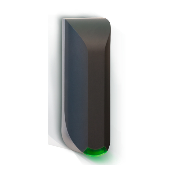
Nedap uPASS Access Installation Manual
Hide thumbs
Also See for uPASS Access:
- Installation manual (19 pages) ,
- Installation manual (23 pages)

Related Manuals for Nedap uPASS Access


Summary of Contents for Nedap uPASS Access
- Page 1 Access installation guide 2020-04-22 | v4.09 | Doc. no. 5281326 www.nedapidentification.com...
-
Page 2: Table Of Contents
Access | installation guide Contents Introduction ..................................4 Firmware versions ..............................4 Supported tags..............................5 Tag security ................................6 Installation ..................................7 Safety instruction ..............................7 Mounting instruction ............................. 7 Antenna coverage ..............................9 Connections ................................... 10 Power supply ..............................10 Communication .............................. - Page 3 Access | installation guide 5.3.5 Read range ..............................29 Firmware update ..............................30 Technical specifications ..............................31 FCC / IC Statement ................................ 32 Part numbers ................................. 33 Disclaimer ..................................33 Document revision ................................ 33 3/33...
-
Page 4: Introduction
Typical applications include hands-free door access in hospitals, office buildings, gated communities, care homes and universities. The uPASS Access is ideal for door post mounting at a height of about 1.5 meters ( ). It can be installed directly 5 feet onto a wall next to a door, without requiring additional mounting accessories. -
Page 5: Supported Tags
These tags are especially programmed in the same format as our TRANSIT tags (Compact-Tag, Window-Button and Heavy-Duty-Tag). The tags will have a customer-code and id-number. The reader will modulate the tag-info onto the Nedap antenna interface output, which can be connected to NEDAP AEOS access control hardware such as the AP1001. -
Page 6: Tag Security
EPC number to ensure that the keys are different for each tag. Required is that the tags contain an EPC Gen2 V2 compliant RFID chip. Refer to NEDAP uPASS how to order guide for product numbers. -
Page 7: Installation
The cable shield shall be connected with safety ground and the metal case of the external device(s). • To be sure of safety, do not modify or add anything to the uPASS Access other than mentioned in this installation •... - Page 8 Install the uPASS Access reader onto the base-plate. Feed the cable through the cable entry hole. Important note: minimum bending radius 30mm. Attach the top of the uPASS Access onto the base-plate. Fix the assembly using the screw on the bottom.
-
Page 9: Antenna Coverage
Access | installation guide 2.3 Antenna coverage The uPASS Access antenna has a detection coverage area as shown in the picture below. The read range, which is up to 2 meters, can be adjusted by means of UHFTOOL software setting. See chapter 5.3.5. -
Page 10: Connections
Shield connected to DC-ground. Connect to metal case of the external device. 3.1 Power supply The uPASS Access requires DC power supply in the range from 12 – 24V. Maximum current consumption is 1A @ 12VDC, 1A @ 24VDC. Connections Power supply 12 - 24VDC. -
Page 11: Communication
Rev. C Figure 4: RS485 point-to-point communication (uPASS Access Rev. C) The uPASS Access reader models before 2020 (Rev. A/B) have a fixed termination resistor. This means you don’t need to install a separate termination resistor. See Figure 5. uPASS HOST 120 Ω... - Page 12 Figure 6: RS485 multi-drop communication Notes The uPASS Access reader models before 2020 (Rev. A/B) have a fixed termination resistor, which cannot not be • disabled. This means that these readers should only be used in point-to-point communication. Use shielded twisted pair cable when extending the RS485 wiring beyond the standard 5 meter cable.
-
Page 13: Usb
USB driver Make sure your computer is connected with internet. Connect the uPASS Access reader to your computer via the USB cable. The USB drivers may be installed automatically. In case you need to install the USB drivers manually, please go to the website www.ftdichip.com/Drivers/VCP.htm... -
Page 14: Wiegand
Access | installation guide 3.2.3 Wiegand The Wiegand and Magstripe ISO7811/2 (clock & data) interface share the same connections. This means that only Wiegand or Magstripe can be used and not both simultaneously Wiegand connections GRAY Data-0 PINK Data-1... -
Page 15: Magstripe Iso7811/2
Access | installation guide 3.2.4 Magstripe ISO7811/2 The Magstripe ISO7811/2 (clock & data) and Wiegand interface share the same connections. This means that only Wiegand or Magstripe can be used and not both simultaneously. Magstripe connections GRAY Clock PINK... -
Page 16: Inputs
Access | installation guide 3.3 Inputs The uPASS Access reader has 3 digital inputs (active low). Connect the input to ground to active the input. Use a potential-free (relay) contact. Leave unconnected otherwise. Connections RED/BLUE Input 0 - LED_UL_IN (active low) -
Page 17: Outputs
Access | installation guide 3.4 Outputs The uPASS Access reader has 2 digital outputs. The function of the digital outputs is dependent upon the installed firmware version. See description below. STANDARD firmware The outputs are used for Wiegand or Magstripe communication. See respectively chapters 3.2.3 or 3.2.4. -
Page 18: Tamper Switch
Access | installation guide 3.5 Tamper switch An internal magnet provides tamper indication when the reader is dismounted. This contact may be connected to an external alarm system. The contacts are normally closed when the reader is in place. -
Page 19: Nedap Antenna Interface
Access | installation guide 3.6 Nedap antenna interface The Nedap antenna interface is used to connect the uPASS Access to NEDAP AEOS access control hardware such as the AP1001. Instead of proximity antenna the uPASS Access can be connected. -
Page 20: Uhf Frequencies
4 UHF frequencies 4.1 Radio regulations The uPASS Access reader operates on the 860 – 960 MHz band. Regulations in this band are not standardized world- wide. Generally the regulations can be divided into several regions. Per region a specific frequency band is available. This frequency band is divided into frequency channels. If local radio regulations require frequency hopping (FHSS), then the uPASS Access automatically selects and uses the available channels. -
Page 21: Reader Configuration
Access | installation guide 5 Reader configuration The uPASS reader settings can be configured easily using the UHFTOOL software. Software developers can find the communication protocol description in the firmware manual. 5.1 UHFTOOL software Figure 9: UHFTOOL software 5.2 Settings Click 'View', 'Show config sidebar' or press F11 to show the configuration sidebar. -
Page 22: Read Data
By default, the reader is configured to select ANY TAG and read its EPC number. Select NEDAP to read only Nedap tags. NEDAP DUAL-ID enables the uPASS to search for Nedap vehicle-id tags. When a vehicle-id tag is found, the uPASS searches for driver-id tags. -
Page 23: Decode Nedap-Xs
Enable decode Nedap-XS when you do not want to use the NEDAP antenna interface. The uPASS will decode the Nedap-XS tag data and output its tag-number in readable format. You can also enable to output or verify the customer code. -
Page 24: Relay / Timing
The 'Vehicle hold time' setting is the time, after a vehicle-id tags has been found, for which the reader will search for driver-id tags. This setting is only used in the NEDAP DUAL-ID mode. The Random off time parameter can be used to enable time sharing between multiple readers on the same frequency. -
Page 25: Led Control
Automatic mode Default the uPASS Access will automatically control the LED. During stand-by the LED will be BLUE and upon identification it will be GREEN. These colors can be changed! -
Page 26: Expert Settings
Wiegand or Magstripe interface. 'Enable vehicle id-events' allows enabling or disabling the id-event messages for vehicle-ids. This may be useful in combination with the NEDAP DUAL-ID mode and an access control panel that does not support the dual-id feature. 26/33... -
Page 27: Output Message Format
Access | installation guide 5.3.2 Output message format Configure output message format. Figure 17: Output message format settings The serial output message format is configurable: <prefix> [<tagstatus>] [<epclen>] [<epc>] [<datlen>] [<data>] <suffix> [ CR/LF ] Example output: 40010257CB21DD0E34244E103FFFC809A862A1EC1500<CR><LF> Customized example Output: X012345<CR><LF>... -
Page 28: Extra Output
Access | installation guide 5.3.3 Extra output Optionally enable Wiegand or Magstripe output for tags that are not programmed by NEDAP in a Wiegand, Magstripe or NEDAP-XS format. 'Protocol': Disabled Do not use the extra output feature. Wiegand Enable Wiegand output. -
Page 29: Frequency
Access | installation guide 5.3.4 Frequency Here is shown the reader's operating frequency region. When frequency hopping is not required, you can select a fixed frequency channel within the available frequency band. Figure 19: Frequency settings 5.3.5 Read range Enable the squelch to reduce the read range. -
Page 30: Firmware Update
Access | installation guide 5.4 Firmware update When the UHFTOOL software is connected to the reader, it automatically checks the firmware version of the reader. If necessary the software recommends to perform a firmware update. Recent reader firmware versions are included within the software. -
Page 31: A Technical Specifications
Access | installation guide A Technical specifications Item Specification Remark Dimensions 150x50x40mm ( 5.9 x 1.9 x 1.5 inch Weight 0.5 kg ( 1.1 lbs Enclosure Polycarbonate (RAL7016) Chassis material Aluminum Zamak (RAL9006) Protection class IP65 (Approx. NEMA4x) Operating temperature -30 °C …... -
Page 32: Bfcc / Ic Statement
Access | installation guide B FCC / IC Statement FCC ID: CGDUPASSREACH IC: 1444A-UPASSRCH This device complies with part 15 of the FCC rules and to RSS210 of Industrial Canada. Operation is subject to the following two conditions: (1) this device may not cause harmful interference, and (2) this device must accept any interference received, including interference that may cause undesired operation. -
Page 33: C Part Numbers
Access | installation guide C Part numbers Readers NEDAP uPASS Access Region 1 (ETSI/EUR 865-868 MHz) 9958240 NEDAP uPASS Access Region 2 (FCC/USA 902-928 MHz) 9206663 NEDAP uPASS Access Region 3 (915-928 MHz) 9211926 D Disclaimer This information is furnished for guidance, and with no guarantee as to its accuracy or completeness; its publication conveys no license under any patent or other right, nor does the publisher assume liability for any consequence of its use;...