Nedap uPASS ACCESS Installation Manual
Hide thumbs
Also See for uPASS ACCESS:
- Installation manual (19 pages) ,
- Installation manual (33 pages)
Table of Contents
Advertisement
Quick Links
Advertisement
Table of Contents

Related Manuals for Nedap uPASS ACCESS


Summary of Contents for Nedap uPASS ACCESS
- Page 1 ACCESS installation guide 2016-03-16 | v4.4 | Doc. no. 5281326...
-
Page 2: Table Of Contents
UPASS ACCESS | INSTALLATION GUIDE Content CONTENT 1 INTRODUCTION _______________________________________________________ 3 SUPPORTED TAGS _______________________________________________ 3 TAG SECURITY __________________________________________________ 3 2 INSTALLATION ________________________________________________________ 5 SAFETY INSTRUCTION ____________________________________________ 5 MOUNTING INSTRUCTIONS _______________________________________ 5 3 CONNECTIONS ________________________________________________________ 7 POWER SUPPLY _________________________________________________ 7 COMMUNICATION _______________________________________________ 7 3.2.1 RS485 ___________________________________________________ 7... -
Page 3: Introduction
(theoretically) cannot be cross-copied. This TID based anti-cloning mechanism is not considered to be a strong protection. NEDAP UHF tags support a locked serialized TID and the uPASS Access reader can be configured to read the TID data field. - Page 4 This feature is supported in combination with all NEDAP UHF tags. By default the uPASS Access reader is configured to read any EPC tag. We encourage customers to enable the TID-check or the two way authentication. But also advise not to completely rely on these methods in high-security applications.
-
Page 5: Installation
The cable shield shall be connected with safety ground and the metal case • of the external device(s). To be sure of safety, do not modify or add anything to the uPASS Access • other than mentioned in this installation guide or indicated by NEDAP N.V. - Page 6 Install the uPASS Access reader onto the base-plate. Feed the cable through the cable entry hole. Important note: minimum bending radius 30mm. Attach the top of the uPASS Access onto the base-plate. Fix the assembly using the screw on the bottom. Figure 2: uPASS Access installation...
-
Page 7: Connections
Cable shield shall be While the shielded USB connected to the metal cable is connected, the The uPASS Access is supplied with a 5 meter (15 feet) shielded cable pigtail with 12 case of the external RS485 interface is disabled! multi-color wires. -
Page 8: Wiegand / Magstripe
Make sure your computer is connected to the internet. The driver should install automatically via Windows update when the uPASS Access reader is connected to your PC via the USB cable. Follow the driver installation wizard. If you do not see the Windows update pop-up, you can manually install the driver. -
Page 9: Led Control
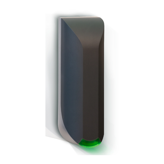
The LED and buzzer can be controlled by the access control system. Automatic mode: Default the uPASS Access will automatically control the LED. During stand-by the LED will be BLUE and upon identification it will be GREEN. These colors can be changed! Remote control: The LED can be controlled remotely by a connected access control system. -
Page 10: Tamper Switch
+24 VDC NEDAP ANTENNA INTERFACE Note The Nedap antenna interface is used to connect the uPASS Access to NEDAP AEOS Extending this connection access control hardware such as the AP1001. Instead of proximity antenna the beyond the 5 meter pig tail uPASS Access can be connected. -
Page 11: Uhf Frequencies
UHF Frequencies UHF FREQUENCIES RADIO REGULATIONS The uPASS Access reader operates on the 860 – 960 MHz band. Regulations in this band are not standardized world-wide. Generally the regulations can be divided into several regions. Per region a specific frequency band is available. This frequency band is divided into frequency channels. -
Page 12: Reader Configuration
By default the reader is configured to select ANY TAG and read its EPC number. Select NEDAP to read only Nedap tags. NEDAP DUAL-ID (introduced in firmware version 2.29) enables the uPASS to search for Nedap vehicle-id tags. When a vehicle-id tag is found, the uPASS searches for driver-id tags. Example 1... -
Page 13: Decode Nedap Xs
Enable decode Nedap XS formatted tags. Introduced in firmware version 2.54. Figure 8: Output settings By default the data on NEDAP XS formatted tags will be transmitted to the TRANSIT compatible processor or the the NEDAP antenna modulation interface. In this case the UPASS will not perform any decoding. -
Page 14: Relay / Timing
The 'Relay hold time' setting is the minimum time the relay is activated. The 'Vehicle hold time' setting is the time, after a vehicle-id tags has been found, for which the reader will search for driver-id tags. This setting is only used in the NEDAP DUAL-ID mode. Introduced in firmware version 2.29. -
Page 15: Expert Settings
Wiegand or magstripe interface. 'Enable vehicle id-events' allows enabling or disabling the id-event messages for vehicle-ids. This may be useful in combination with the NEDAP DUAL-ID mode and an access control panel that does not support the dual-id feature. -
Page 16: Extra Output
<prefix> [<tagstatus>] [<epclen>] [<epc>] [<datlen>] [<data>] <suffix> [ CR/LF ] 5.3.3 EXTRA OUTPUT Optionally enable Wiegand or magstripe output for tags that are not programmed by Nedap in a Wiegand, magstripe or nedap-xs format. This feature is introduced in firmware version 2.13 or newer. 'Protocol': Disabled Do not use the additional output feature. -
Page 17: Frequency
UPASS ACCESS | INSTALLATION GUIDE Reader Configuration Example 1 Output a Wiegand 26-bit message with facility code 10: Figure 13: Additional output example 1 Example 2 Output the 13 rightmost digits from the EPC number using the magstripe interface: Figure 14: Additional output example 2 5.3.4 FREQUENCY... -
Page 18: Read Range
UPASS ACCESS | INSTALLATION GUIDE Reader Configuration 5.3.5 READ RANGE Enable the squelch to reduce the read range. This is useful to optimize lane separation. When the squelch is enabled, you can set the squelch level. This level ensures that only tags with a returned signal strength higher than the squelch level are identified. -
Page 19: Atechnical Specifications
UPASS ACCESS | INSTALLATION GUIDE Technical Specifications TECHNICAL SPECIFICATIONS Item Specification Remark Dimensions 150x50x40mm ( 5.9 x 1.9 x 1.5 inch Weight 0.5 kg 1.1 lbs Enclosure Polycarbonate RAL7016) Chassis material Aluminum (Zamak5) RAL9006) Protection class IP65 Approx. NEMA4x) -30 °C … + 60 °C Operational (-22°F …... -
Page 20: Bpart Numbers
UPASS ACCESS | INSTALLATION GUIDE Part Numbers PART NUMBERS Readers NEDAP uPASS Access Region 1 9958240 (EUR 865-868 MHz) 9206663 NEDAP uPASS Access Region 2 9211926 (USA 902-928 MHz) NEDAP uPASS Access Region 3 (915-928 MHz) 20/23... -
Page 21: Cfcc / Ic Statement
UPASS ACCESS | INSTALLATION GUIDE FCC / IC statement FCC / IC STATEMENT FCC ID: CGDUPASSACC IC: 1444A-UPASSACC Compliace statement: This device complies with part 15 of the FCC rules and to RSS210 of Industrial Canada. Operation is subject to the following two conditions:... -
Page 22: Ddisclaimer
UPASS ACCESS | INSTALLATION GUIDE Disclaimer DISCLAIMER This information is furnished for guidance, and with no guarantee as to its accuracy or completeness; its publication conveys no license under any patent or other right, nor does the publisher assume liability for any consequence of its use; specifica- tions and availability of goods mentioned in it are subject to change without notice;... -
Page 23: Edocument Revision
UPASS ACCESS | INSTALLATION GUIDE Document revision DOCUMENT REVISION Version Date Comment 2016-03-16 Updated frequency regions 2015-07-29 UL update 2015-03-17 Notes page 7 - extension lengths adjusted 2015-02-19 Duplicate content deleted 2014-02-11 Layout adjusted to new corporate style 23/23...