Nedap TRANSIT ENTRY Installation Manual
Hide thumbs
Also See for TRANSIT ENTRY:
- Quick reference (7 pages) ,
- Installation manual (27 pages) ,
- Quick reference (4 pages)
Table of Contents
Advertisement
Quick Links
Advertisement
Table of Contents

Related Manuals for Nedap TRANSIT ENTRY


Summary of Contents for Nedap TRANSIT ENTRY
- Page 1 TRANSIT ENTRY installation guide 2015-08-24 | v4.1 | 5268605...
-
Page 2: Table Of Contents
TRANSIT ENTRY | INSTALLATION GUIDE Content CONTENT 1 INTRODUCTION _______________________________________________________ 3 PRODUCT DESCRIPTION __________________________________________ 3 OPTIONAL CARD TECHNOLOGY READER INTERFACE __________________ 3 2 INSTALLATION ________________________________________________________ 4 SAFETY PRECAUTIONS ___________________________________________ 4 MOUNTING INSTRUCTIONS _______________________________________ 4 ADJUSTABLE MOUNTING BRACKET _________________________________ 5 OPENING THE SERVICE COVER ____________________________________ 6... -
Page 3: Introduction
(12 feet) to present a card. The hands free access system is made up of a TRANSIT Entry reader and a transponder. TRANSIT Entry readers are installed next to a door or gate. A long range transponder visible in line of sight of the reader will be identified at distances up to... -
Page 4: Installation
Disconnect the power supply before removing or installing any parts. • To be sure of safety, do not modify or add anything to the TRANSIT Entry • other than mentioned in this installation guide or indicated by NEDAP N.V. -
Page 5: Adjustable Mounting Bracket
Once the adjustable mounting bracket is assembled, attach the bracket to the wall or mast. After that the TRANSIT Entry can be mounted onto the bracket. The ball and socket joint can be used to adjust the reader’s orientation. Tighten the hex screw on top of the joint to fix the correct orientation. -
Page 6: Opening The Service Cover
Make sure to follow all safety precautions outlined in chapter 2.1 and disconnect the power supply when installing or replacing an optional interface board. AVAILABLE INTERFACE BOARDS Various optional interface boards are also available for the TRANSIT Entry. Ethernet (TCP/IP) interface board Connects the TRANSIT Entry to an Ethernet network using the TCP/IP protocol. - Page 7 Installation Installation Procedure Disconnect the power supply. Remove the complete front cover from the TRANSIT Entry. Place the interface board on the 14-pin header K1. Make sure it’s firmly positioned and makes good contact with connector K1. Figure 5: interface board installation Tighten the two screws to fix the board into place.
-
Page 8: Connections
TRANSIT ENTRY | INSTALLATION GUIDE Connections CONNECTIONS CABLE CONNECTIONS Cable connections to the TRANSIT Entry are made using the EMC cable glands. Shielded cable shall be used for all connections including the DC-supply connection. Assembly instructions: Push the cap nut (1),... -
Page 9: Wire Connections
POWER SUPPLY Note The TRANSIT Entry requires DC power supply in the range from 12 – 24V. Maximum The power supply current consumption is 1A @ 12VDC, 0.5A @ 24VDC. -
Page 10: Communication
3.4.1 RS232 CONNECTION Maximum cable length of 15 meters (50 feet) or the The TRANSIT Entry has an on-board RS232 interface. This interface does not support cable length equal to a any hardware handshake signals. The communication protocol, baud rate, data capacitance of 2500pF. -
Page 11: Rs422 Connection
TRANSIT ENTRY | INSTALLATION GUIDE Connections 3.4.2 RS422 CONNECTION Note The TRANSIT Entry has an on-board RS422 interface. The communication protocol, Maximum cable length baud rate, data format and flow control depend upon the reader firmware. See 1200 meters (4000 feet). -
Page 12: Wiegand, Magstripe, Barcode Connection
TRANSIT ENTRY | INSTALLATION GUIDE Connections Note 3.4.3 WIEGAND, MAGSTRIPE, BARCODE CONNECTION Maximum cable length 150 The synchronous communication interface wiring depends upon the selected meters (500 feet) communication protocol and the reader firmware. Please refer to the firmware manual for more details. -
Page 13: Usb Connection
Make sure your computer is connected to the internet. The driver should install automatically via Windows update when the TRANSIT Entry is connected to your PC via the USB cable. Follow the driver installation wizard. If you do not see the Windows update pop-up, you can manually install the driver. -
Page 14: Digital I/O
TRANSIT ENTRY | INSTALLATION GUIDE Connections DIGITAL I/O 3.5.1 RELAY OUTPUT The relay output is automatically activated upon identification of a transponder. This behavior can be changed and configured by means of the firmware. Please refer to the firmware manual for more details. -
Page 15: Read Disable Input
Connections 3.5.2 READ DISABLE INPUT The reading of the TRANSIT Entry can be completely disabled with the RDIS input. This input is commonly used in combination with a sensor (e.g. inductive loop) that detects the presence of a person or vehicle. Use always a relay contact to connect the internal 5V to the RDIS input. -
Page 16: General Purpose Inputs
TRANSIT ENTRY | INSTALLATION GUIDE Connections 3.5.3 GENERAL PURPOSE INPUTS Three general purpose inputs are available on the TRANSIT Entry reader. The inputs are active low. Connections General purpose input 1 General purpose input 2 General purpose input 3 Ground... -
Page 17: General Purpose Outputs
TRANSIT ENTRY | INSTALLATION GUIDE Connections 3.5.4 GENERAL PURPOSE OUTPUTS Three general purpose inputs are available on the TRANSIT Entry reader. The installed firmware may use these outputs for synchronous communication interfaces such as Wiegand, Barcode and Magstripe. See chapter 3.4.3 for more details. -
Page 18: Tamper Switch
An internal magnet provides tamper indication when the service cover is opened. This contact may be connected to an external alarm system. The contacts are normally closed when the cover is in place. Tamper switches of multiple TRANSIT Entry reader may be connected in series. Connections Tamper switch (normally closed) -
Page 19: Special Connections
SPECIAL CONNECTIONS Nedap Antenna Interface Note The Nedap antenna interface is used to connect the TRANSIT Entry to NEDAP EAOS Use coax RG58U, maximum access control hardware such as the AP1001. Instead of proximity antenna the cable length 100 meters TRANSIT Entry can be connected. -
Page 20: Dip Switch Settings
TRANSIT ENTRY | INSTALLATION GUIDE DIP Switch Settings DIP SWITCH SETTINGS The DIP-switches are located behind the service cover. The function of the switches SW2-1 through SW2-8 is dependent upon the installed firmware. Please refer to the firmware manual for details. -
Page 21: Led Indications
TRANSIT ENTRY | INSTALLATION GUIDE LED Indications LED INDICATIONS A number of LED’s indicate the current status of the TRANSIT Entry reader. Figure 21: LED locations Table 1 below describes the function of each LED. Description LED bar indicating the received tag signal strength. This LED bar may also indicate the presence of radio interference. -
Page 22: Frequency Selection
TRANSIT ENTRY | INSTALLATION GUIDE Frequency Selection FREQUENCY SELECTION The TRANSIT Entry reader operates in the 2.45GHz frequency band. When two or more readers are within a range of 15 meters , these readers should be set (50 feet) on a different operating frequency. The selected frequency has to comply with local radio regulations. -
Page 23: Read Range Control (Squelch)
READ RANGE CONTROL (SQUELCH) PRINCIPLE The read range of the TRANSIT Entry can be controlled with the embedded squelch function. The squelch references the received signal strength against the squelch level setting. When the received signal strength is below the squelch level no identification is possible. -
Page 24: Identification
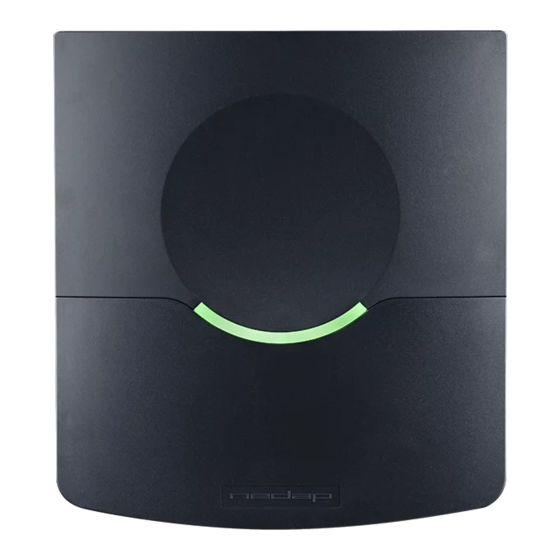
Identification IDENTIFICATION The TRANSIT Entry reader is always reading (except when disabled with the read disable input, see chapter 3.5.2). Automatically upon identification of a transponder the relay will be activated, the ‘smile’ lights-up and an event message is generated on the communication interface(s). -
Page 25: Firmware Upgrade
FIRMWARE UPGRADE Note Aborted downloads may The firmware in the TRANSIT Entry’s processor can be upgraded by means of the cause the reader to stop serial interface (RS232, RS422 or USB). The upgrade is performed by the ‘PIC functioning. In such cases downloader’... -
Page 26: Atechnical Specifications
TRANSIT ENTRY | INSTALLATION GUIDE Technical Specifications TECHNICAL SPECIFICATIONS Item Specification Remark Dimensions 200x220x46.5mm 7.87 x 8.66 x 1.83 inch Weight 0.75 kg ( 1.65 lbs Enclosure color RAL7017 (dark gray) Enclosure material Polycarbonate Chassis material Aluminum Cable entry fittings... -
Page 27: Bpart Numbers
TRANSIT ENTRY | INSTALLATION GUIDE Part Numbers PART NUMBERS Readers TRANSIT Entry 9876200 Accessories Ethernet (TCP/IP) board 7817940 MTR Module 7816650 HID interface board 7819102 Adjustable mounting 9875840 bracket Transponders Compact Tag 9891900 Window Button 9882650 Window Button Switch 9882480... -
Page 28: Cfcc / Ic Statement
TRANSIT ENTRY | INSTALLATION GUIDE FCC / IC Statement FCC / IC STATEMENT FCC ID: CGD-TRANSITENTRY IC: 1444A-TRANSITE This device complies with part 15 of the FCC Rules and to RSS210 of Industry Canada. Operation is subject to the following two conditions: (1) this device may not cause harmful interference, and (2) this device must accept any interference received, including interference that may cause undesired operation. -
Page 29: Ddisclaimer
TRANSIT ENTRY | INSTALLATION GUIDE Disclaimer DISCLAIMER This information is furnished for guidance, and with no guarantee as to its accuracy or completeness; its publication conveys no license under any patent or other right, nor does the publisher assume liability for any consequence of its use; specifica- tions and availability of goods mentioned in it are subject to change without notice;... -
Page 30: Edocument Revision
TRANSIT ENTRY | INSTALLATION GUIDE Document revision DOCUMENT REVISION Version Date Comment 2015-08-24 Document number on front page 2014-02-11 Layout adjusted to new corporate style 30/30...