Advertisement
Quick Links
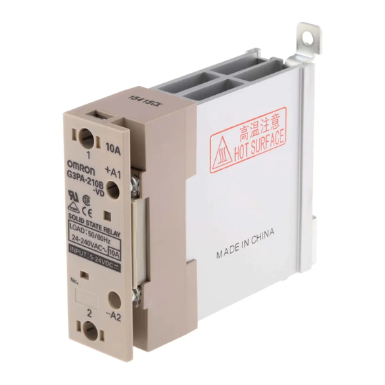
Power Solid-state Relay
Extremely Thin Relays Integrated with
Heat Sink
Downsizing achieved through optimum design of
heat sink.
Mounting possible via screws or via DIN rail.
Close mounting possible for linking terminals.
(Except for G3PA-260B-VD.)
Applicable with 3-phase loads.
Replaceable power element cartridges.
Conforms to VDE 0160 (finger protection), with a
dielectric strength of 4,000 V between input and
load.
Conforms to VDE 0805, IEC 950.
Approved by UL, CSA, and VDE.
Ordering Information
Model
Isolation
Phototriac
o o ac
G3PA-210B-VD
coupler
l
G3PA-220B-VD
G3PA-240B-VD
G3PA-260B-VD
G3PA-210BL-VD
G3PA-220BL-VD
G3PA-240BL-VD
G3PA-260BL-VD
G3PA-210B-VD
G3PA-220B-VD
G3PA-240B-VD
G3PA-260B-VD
G3PA-420B-VD
G3PA-430B-VD
G3PA-420B-VD-2
G3PA-430B-VD-2
G3PA-450B-VD-2
132
Zero cross function
Yes
es
No
o
Yes
es
Indicator
Applicable output load
Yes
es
10 A at 24 to 240 VAC
20 A at 24 to 240 VAC
40 A at 24 to 240 VAC
60 A at 24 to 240 VAC
10 A at 24 to 240 VAC
20 A at 24 to 240 VAC
40 A at 24 to 240 VAC
60 A at 24 to 240 VAC
10 A at 24 to 240 VAC
20 A at 24 to 240 VAC
40 A at 24 to 240 VAC
60 A at 24 to 240 VAC
20 A at 180 to 400 VAC
30 A at 180 to 400 VAC
20 A at 200 to 480 VAC
30 A at 200 to 480 VAC
50 A at 200 to 480 VAC
G3PA-(VD)
RCW
Rated input voltage
5 o
5 to 24 VDC
C
24 VAC
C
12 to 24 VDC
o
C
Advertisement

Related Manuals for Omron G3PA-VD Series


Summary of Contents for Omron G3PA-VD Series
- Page 1 Power Solid-state Relay G3PA-(VD) Extremely Thin Relays Integrated with Heat Sink Downsizing achieved through optimum design of heat sink. Mounting possible via screws or via DIN rail. Close mounting possible for linking terminals. (Except for G3PA-260B-VD.) Applicable with 3-phase loads. Replaceable power element cartridges.
- Page 2 G3PA-(VD) G3PA-(VD) Replacement Parts Name Carry current Model Applicable SSR Power Device Cartridge e ce Ca 10 A G32A-A10-VD DC5-24 G3PA-210B-VD DC5-24 G32A-A10L-VD DC5-24 G3PA-210BL-VD DC5-24 G32A-A10-VD AC24 G3PA-210B-VD AC24 20 A G32A-A20-VD DC5-24 G3PA-220B-VD DC5-24 G32A-A20L-VD DC5-24 G3PA-220BL-VD DC5-24 G32A-A20-VD AC24 G3PA-220B-VD AC24 40 A...
- Page 3 G3PA-(VD) G3PA-(VD) Output Model Applicable load Load voltage Load current Inrush current G3PA-210B(L)-VD 19 to 264 VAC (50/60 Hz) 9 o 6 C (50/60 0.1 to 10 A 150 A (60 Hz, 1 cycle) G3PA-220B(L)-VD 0.1 to 20 A 220 A (60 Hz, 1 cycle) G3PA-240B(L)-VD 0.5 to 40 A 440 A (60 Hz, 1 cycle)
- Page 4 G3PA-(VD) G3PA-(VD) Engineering Data Load Current vs. Ambient Temperature Characteristics Horizontal Mounting to Ground Panel É É É É É Ground G3PA-210B(L)-VD, G3PA-220B(L)-VD G3PA-240B(L)-VD G3PA-260B(L)-VD G3PA-220B(L)-VD G3PA-210B(L)-VD –30 –20 Ambient temperature ( C) Ambient temperature ( C) Ambient temperature ( C) G3PA-420B-VD, G3PA-420B-VD-2 G3PA-430B-VD, G3PA-430B-VD-2 G3PA-450B-VD-2...
- Page 5 G3PA-(VD) G3PA-(VD) Characteristics Between Input Voltage and Input Current G3PA-2j0B-VD G3PA-4jB-VD Input voltage (V) Input voltage (V) Vertical Mounting to Ground Panel É É É É É Ground É É É É É G3PA-210B(L)-VD, G3PA-220B(L)-VD G3PA-240B(L)-VD G3PA-260B(L)-VD G3PA-220B(L)-VD G3PA-210B(L)-VD –30 –20 Ambient temperature ( C) Ambient temperature ( C)
- Page 6 G3PA-(VD) G3PA-(VD) Close Mounting (Up to Three) Panel É É É É É Ground DIN track G3PA-210B(L)-VD, G3PA-220B(L)-VD G3PA-240B(L)-VD G3PA-260B(L)-VD G3PA-220B-VD G3PA-210B-VD –30 –20 Ambient temperature ( C) Ambient temperature ( C) Ambient temperature ( C) G3PA-420B-VD, G3PA-420B-VD-2 G3PA-430B-VD, G3PA-430B-VD-2 –30 –30 Ambient temperature ( C)
- Page 7 G3PA-(VD) G3PA-(VD) Inrush Current Resistivity Non-repetitive (Keep the inrush current to half the rated value if it occurs repetitively.) G3PA-210B(L)-VD G3PA-220B(L)-VD G3PA-240B(L)-VD/260B(L)-VD Energizing time (ms) Energizing time (ms) Energizing time (ms) G3PA-420B-VD, G3PA-420B-VD-2 G3PA-430B-VD, G3PA-430B-VD-2, G3PA-450B-VD-2 Energizing time (ms) Energizing time (ms)
- Page 8 G3PA-(VD) G3PA-(VD) Nomenclature Protective cover Operation indicator Temperature indicator Power Device Cartridge Note: Use the special tool for replacement of the cartridge (G3PA-210B-VD/-220B-VD models only). Linking terminal (except for G3PA-260B-VD) Heat sink G3PA-210B-VD G3PA-220B-VD DIN track mounting part G3PA-240B-VD G3PA-260B-VD Mounting hole (G3PA-220B-VD) Protective...
- Page 9 G3PA-(VD) G3PA-(VD) Operation Renewal Parts G32A-A Power Device Cartridge The G32A-A Power Device Cartridge (a Triac Unit) can be replaced with a new one. When the temperature indicator has changed from pink to red, the triac circuitry may have malfunctioned possibly by an excessive flow of current, in which case, dismount the damaged cartridge for replacement.
- Page 10 G3PA-(VD) G3PA-(VD) Note: 1. Replacing Power Device Cartridges When replacing Power Device Cartridges, use the specified model. Using a Power Device Cartridge other than the specified one will result in faulty operation and destruction of the elements. 2. Noise Terminal Voltage according to EN55011 Conformance to EN55011 is possible if a capacitor is connected to the load power supply as shown in the diagram below.
- Page 11 G3PA-(VD) G3PA-(VD) G32A-A10/G32A-A20 Use the special tool (provided) to extract the cartridge for replace- ment with a new one. Extraction Follow the procedures below to dismount the Power Device Car- tridge from the G3PA. 1. Switch off the power. Apply silicone grease here. 2.
- Page 12 G3PA-(VD) G3PA-(VD) G32A-A40-VD/G32A-A60-VD/G32A-A430-VD The G32A Power Device Cartridge is mounted and secured with screws to the G3PA Unit. Extraction Mounting Follow the procedures below to dismount the G32A-A Power De- 1. Apply silicone grease to the entire surface of the heat radiator. vice Cartridge from the G3PA.
- Page 13 G3PA-(VD) G3PA-(VD) Linking Terminal Connection Connecting with linking terminal for G3PA-210B-VD, Connecting with linking terminal for G32A. -220B-VD, -240B-VD and G3PA-420B-VD, G3PA-430B-VD. G32A Unit G32A Unit SSR1 SSR2 SSR1 SSR2 * The cover will not fit if the terminal protrudes. 1.
- Page 14 G3PA-(VD) G3PA-(VD) Horizontal Mounting Screw or DIN track mounting is possible. Mount horizontally to ground. Panel É É É É É Ground Close Mounting Close mounting of up to three G3PA Keep a distance of 80 mm between SSRs is possible. the upper SSR and the lower SSR.
- Page 15 G3PA-(VD) G3PA-(VD) Dimensions Note: All units are in millimeters unless otherwise indicated. G3PA-210B-VD Without Terminal Cover With Terminal Cover 4.6 dia. Two, M4 Linking terminal Two, M3.5 Linking terminal 4.6 x 5.6 elliptical hole 100 max. Mounting Holes Terminal Arrangement/ Internal Connections Two, 4.5 dia.
- Page 16 G3PA-(VD) G3PA-(VD) G3PA-220B-VD Without Terminal Cover With Terminal Cover 4.6 dia. Two, M4 Linking terminal Two, M3.5 Linking terminal 4.6 x 5.6 elliptical hole 100 max. Mounting Holes Terminal Arrangement/ Internal Connections Two, 4.5 dia. or M4 holes...
- Page 17 G3PA-(VD) G3PA-(VD) G3PA-240B-VD Without Terminal Cover With Terminal Cover 4.6 dia. Two, M5 Linking terminal B1 Two, M3.5 Linking terminal B2 4.6 x 5.6 elliptical hole Mounting Holes Terminal Arrangement/ Internal Connections Two, 4.5 dia. or M4 holes 100 max.
- Page 18 G3PA-(VD) G3PA-(VD) G3PA-260B-VD G3PA-450B-VD-2 Without Terminal Cover With Terminal Cover 4.6 dia. Two, M5 Two, M3.5 4.6 x 5.6 elliptical hole 110 max. 100 max. Mounting Holes Terminal Arrangement/ Internal Connections Two, 4.5 dia. or M4 holes...
- Page 19 G3PA-(VD) G3PA-(VD) G3PA-420B-VD, G3PA-420B-VD-2 Terminal Arrangement/ Internal Connections Mounting Holes Two, 4.5 dia. or M4 4.6 dia. Two, M4 90 0.2 Linking terminal max. Linking 90 0.3 terminal Two, M3.5 25 0.2 37 max. 100 max. 4.5 x 5.6 elliptic hole 25 0.3 13.2 G3PA-430B-VD, G3PA-430B-VD-2...
- Page 20 G3PA-(VD) G3PA-(VD) ALL DIMENSIONS SHOWN ARE IN MILLIMETERS. To convert millimeters into inches, multiply by 0.03937. To convert grams into ounces, multiply by 0.03527. Cat. No. K094-E1-3B...