
Related Manuals for Ferroli UT REC


Summary of Contents for Ferroli UT REC
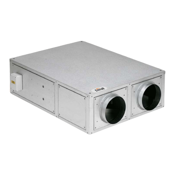
- Page 1 RECUPERATORI DI CALORE HEAT RECOVERY UNITS UT REC – UT REC C UT REC V UT REC R MANUALE DI INSTALLAZIONE E USO INSTALLATION AND OPERATION MANUAL...
-
Page 3: Symbols Used
SIMBOLOGIA SYMBOLS USED AVVERTENZA WARNING PERICOLO DANGER PERICOLO RISCHIO DI SCOSSE ELETTRICHE DANGER RISK OF ELECTRIC SHOCK ATTENZIONE SOLO PERSONALE AUTORIZZATO ATTENTION ONLY AUTHORISED STAFF DIVIETO PROHIBITION IDENTIFICAZIONE UNITA’ IDENTIFICATION OF THE UNIT Modello / Model Numero di matricola / Serial number Tensione [V] / Voltage [V] Numero di fasi / Number of phases Frequenza di rete [Hz] / Frequency [Hz]... - Page 4 pag. 4...
- Page 5 INDEX INDICE INTRODUCTION page 6 INTRODUZIONE pag. 6 PRESENTATION OF THE MANUAL page 7 PRESENTAZIONE MANUALE pag. 7 1 - GENERAL CHARACTERISTICS 1 - CARATTERISTICHE TECNICHE 1.1 General characteristics page 07 1.1 Caratteristiche generali pag. 07 unit technical data page 08 UT-REC/UT-REC E-UT-REC C/UT-REC CE 1.2 Dati tecnici unità...
- Page 6 INTRODUZIONE INTRODUCTION Le unità di recupero di calore prodotte da FERROLI sono caratterizzate da The heat recovery units manufactured by FERROLI feature compact ridotte dimensioni e facilità di montaggio e permettono di coniugare il dimensions and easy assembly, combining maximum room comfort with certain massimo comfort ambientale con un sicuro risparmio energetico.
-
Page 7: Caratteristiche Tecniche
PRESENTAZIONE MANUALE PRESENTATION OF THE MANUAL Questo manuale riporta le informazioni e quanto ritenuto necessario per il This manual describes the rules for the transportation, the installation, the trasporto, l'installazione, l'uso e la manutenzione dei recuperatori di calore. use and the maintenance of the heat recovery. The user will find everything L'utente troverà... - Page 8 1.2 DATI TECNICI UNITÀ UT-REC / UT-REC E – UT-REC C / UT-REC CE 1.2 UT-REC / UT-REC E – UT-REC C / UT-REC CE UNIT TECHNICAL DATA MODELLO / MODEL UT-REC, UT-REC C Portata aria nominale / Nominal air flow 1580 1850 2250...
- Page 9 1.2 ORIENTAMENTI POSSIBILI UT-REC / UT-REC E – UT REC C / UT-REC / UT-REC E – UT REC C / UT-REC CE POSSIBLE UT-REC CE In funzione della configurazione della rete e dello spazio CONFIGURATIONS According to the configuration of the installation and the space available, both for horizontal and vertical models one disponibile è...
- Page 10 By pass free cooling. Bypass for free cooling. Per i modelli orizzontali The structure of horizontal models UT-REC / UT-REC E UT-REC C / UT-REC CE UT-REC / UT-REC E UT-REC C / 110 al 530 con orientamento tipo 03 o tipo 04, la carpenteria presenta from 110 to 530 with configuration type 03 or 04, features a UT-REC CE un pre taglio allo scopo di consentire l’secuzione di by-pass per free...
- Page 11 1.3.2 ORIENTAMENTI MODELLI VERTICALI / VERTICAL MODELS CONFIGURATIONS ORIENTAMENTI TIPO 01 / CONFIGURATIONS TYPE 01 ORIENTAMENTI TIPO 02 / CONFIGURATION STYPE 02 01 D 01 S 02 D 02 S Aria espulsa / Exhaust air Aria espulsa / Exhaust air Aria di rinnovo / Fresh air Aria di rinnovo / Fresh air ORIENTAMENTI TIPO 03 / CONFIGURATIONS TYPE 03...
-
Page 12: Dimensioni E Pesi
1.4 DIMENSIONI E PESI 1.4 DIMENSIONS AND WEIGHTS 1.4.1 Dimensioni modelli orizzontali 1.4.1 Dimensions of the horizontal models UT-REC/UT-REC E – UT-REC C / UT-REC CE UT-REC/UT-REC E – UT-REC C / UT-REC CE Dimensione / Dimension Peso / Weight Modello [kg] Model... - Page 13 1.4.2 Dimensioni modelli verticali 1.4.2 Dimensions of the vertical models Dimensione / Dimension Peso / Weight Modello [kg] [mm] [mm] [mm] [mm] [mm] [mm] [mm] [mm] [mm] [mm] [mm] [mm] Model [mm] [mm] 0 gas (41) (45) 1140 (77) 1300 (118) 1380 (130)
- Page 14 1.5 UT-REC R / UT-REC RE UNIT TECHNICAL DATA 1.5 DATI TECNICI UNITÀ UT-REC R / UT-REC RE MODELLO / MODEL UT-REC R 1050 1800 2220 2600 3250 4290 5300 Portata aria nominale / Nominal air flow Pressione statica utile/ External static pressure Assorbimento max.
- Page 15 1.6 UT-REC R / UT-REC RE POSSIBLE CONFIGURATIONS 1.6 ORIENTAMENTI POSSIBILI UT-REC R / UT-REC RE ORIENTAMENTO TIPO 01 / CONFIGURATION TYPE 01 ORIENTAMENTO TIPO 02 / CONFIGURATION TYPE 02 (Tipo standard / Standard type) LATO ESTRAZIONE ROTORE EXCHANGER EXTRACTION SIDE LATO ESTRAZIONE ROTORE EXCHANGER EXTRACTION SIDE Aria espulsa / Exhaust air...
- Page 16 1.8 ACCESSORI 1.8 ACCESSORIES • Electric post-heating section - BE • Resistenza elettrica di post-riscaldamento - BE • Batteria interna di post-riscaldamento ad acqua (mod. 110÷530) - BW • Post-heating internal water coil (mod. 110÷530) - BW (solo per serie UT-REC / UT-REC E e UT-REC C / UT-REC CE) (only for UT-REC / UT-REC E and UT-REC C / UT-REC CE series) •...
- Page 17 1.8.3 SEZIONE CON BATTERIA AD ACQUA CALDO/FREDDO - BFW 1.8.3 COLD/HOT WATER COIL SECTION - BFW Il modulo contiene una batteria ad acqua per post-riscaldamento o The module contains a water coil (for both post-heating and cooling) and raffrescamento e va posizionato esternamente alla macchina davanti alla has to be located outside the unit in front of the supply air inlet.
- Page 18 1.8.5 SERVOMOTORI PER SERRANDE - SC / SCR 1.8.5 DAMPER ACTUATORS - SC / SCR I servomotori per serrande consentono la motorizzazione della The actuators are suitable to be installed with the SR front dampers. serranda frontale SR. Technical characteristics - SC230: power supply 230V, 2-, 3- point control signal Caratteristiche tecniche - SC230: alimentazione 230V, controllo 2/3 punti...
- Page 19 1.8.9 PANNELLO DI CONTROLLO UNITÀ – PCO10 1.8.9 UNIT CONTROL PANEL – PCO10 Il pannello, per installazione a parete, consente il controllo della The panel is suitable for wall mounting, and is used to control the room temperatura ambiente inverno/estate, dà il consenso per l’attivazione o temperature both in heating and cooling operation, to enable or disable l'esclusione della batteria ad acqua o della resistenza elettrica e the water coil or the electric heater, and to select the fan operating...
- Page 20 1.8.12 PANNELLO DI CONTROLLO UNITÀ - PC10R 1.8.12 UNIT CONTROL PANEL - PC10R Idoneo per installazione a parete, consente il controllo della temperatura Suitable for wall mounting, this control panel can be used to control the ambiente in modalità riscaldamento/raffreddamento, attraverso controllo room temperature on both heating and cooling operation, by 0-10V con- modulante 0-10V di servocomandi valvole per acqua (o, in alternativa, trol signal for hot7cold water valve s or, as an alternative, by onloff...
-
Page 21: Installazione E Messa In Servizio
2 - TRASPORTO 2 - TRANSPORT 2.1 Imballaggio 2.1 Packaging • I recuperatori e i loro accessori sono inseriti in scatole di cartone che • The heat recovery unit and their accessories are inserted into cardboard dovranno rimanere integre fino al momento del montaggio. boxes (or polyethylene bubble pack), which must remain integral until •... - Page 22 N.B. L'installatore e l'utilizzatore nell'uso del recuperatore devono tenere N.B. When using the heat recovery unit, the installer and user must con- conto e porre rimedio a tutti gli altri tipi di rischio connessi con l'impianto. sider and solve all risks connected to theplant. For example, risks deri- Ad esempio rischi derivanti da ingresso di corpi estranei, oppure rischi ving from the entry of foreign bodies or risks due to the conveying of dan- dovuti al convogliamento di gas pericolosi infiammabili o tossici ad alta...
- Page 23 3.5 Posizionamento della macchina 3.5 Positioning of the machine Qui di seguito sono illustrate alcune sequenze del montaggio: Some assembly sequences are illustrated below: 1. Eseguire la foratura a soffitto e fissare quattro tiranti filettati M8 come 1. Drill the ceiling and fix four M8 threaded tie-rods, as indicated in the indicato in figura.
- Page 24 • Il sifone deve infine essere dotato di tappo per la pulizia nella parte bassa o • The siphon must finally have a cap for cleaning the lower part or must deve comunque permettere un veloce smontaggio per la pulizia periodica however allow quick disassembly for periodical cleaning •...
- Page 25 3.8 Sezione con batteria ad acqua SBFR 3.8 Water coil section SBFR Attenzione: l’installazione della sezione con batteria ad acqua compor- Attention: the installation of the section with water coil leads to additio- ta perdite di carico aggiuntive nel circuito di immissione. Tali pedite nal pressure drops in the introduction circuit.
- Page 26 3.8.1 Collega ento idraulici sezione BFW 3.8.1 BFW section hydraulic connections • Le operazioni di installazione e collegamento delle tubazioni sono • The installation and connection operations of the pipes are opera- operazioni che possono compromettere il buon funzionamento del- tions that can compromise the good functioningof the plant or l'impianto o, peggio, causare danni irreversibili alla macchina.
-
Page 27: Collegamenti Elettrici
4 - COLLEGAMENTI ELETTRICI 4 - ELECTRIC CONNECTIONS Prima di iniziare qualsiasi operazione assicurarsi che la Before starting any operation, make sure that the main linea di alimentazione generale sia sezionata power supply line has been isolated • I collegamenti elettrici ai quadri di comando devono essere effettuati •... - Page 28 4.1.4 Pannello di controllo unità - PCO 4.1.4 Unit control panel - PCO 1. Sfilare la manopola 1. Take out the knob 2. Rimuovere la calotta 2. Remove the cap. 3. Sganciare la piastra attaccata alla base del termostato e al contempo 3.
-
Page 29: Schema Elettrico
4.2 UT-REC – UT-REC E series wiring diagrams 4.2 Schemi elettrici Serie UT-REC – UT-REC E SCHEMA ELETTRICO UT-REC / UT-REC C 33 - 55 DIRETTO WIRING DIAGRAM UT-REC / UT-REC C 33 - 55 DIRECT SCHEMA ELETTRICO UT-REC / UT-REC C 33 - 55 con REGOLATORE ELETTRONICO VVM WIRING DIAGRAM UT-REC / UT-REC C 33 - 55... - Page 30 SCHEMA ELETTRICO UT-REC / UT-REC C 110 – 175 – 220 DIRETTO WIRING DIAGRAM UT-REC / UT-REC C 110 – 175 – 220 DIRECT SCHEMA ELETTRICO UT-REC / UT-REC C 110 – 175 – 220 con SELETTORE DI VELOCITÀ COM3 COM3 WIRING DIAGRAM UT-REC / UT-REC C 110 –...
- Page 31 SCHEMA ELETTRICO UT-REC / UT-REC C 110 – 175 – 220 con RESISTENZA ELETTRICA BE e PANNELLO DI CONTROLLO PCO WIRING DIAGRAM UT-REC / UT-REC C 110 – 175 – 220 with BE HEATING SECTION and PCO CONTROL PANEL SCHEMA ELETTRICO UT-REC / UT-REC C 255 –...
- Page 32 SCHEMA ELETTRICO UT-REC / UT-REC C 255 – 320 con PANNELLO DI CONTROLLO PCO WIRING DIAGRAM UT-REC / UT-REC C 255 – 320 with PCO CONTROL PANEL SCHEMA ELETTRICO UT-REC / UT-REC C 255 – 320 con RESISTENZA ELETTRICA BE e PANNELLO DI CONTROLLO PCO WIRING DIAGRAM UT-REC / UT-REC C 255 - 320...
- Page 33 SCHEMA ELETTRICO UT-REC / UT-REC C 410-530 (TRIFASE) con PANNELLO DI CONTROLLO PCO WIRING DIAGRAM UT-REC / UT-REC C 410-530 (THREE- PHASE) with PCO CONTROL PANEL SCHEMA ELETTRICO UT-REC / UT-REC C 410-530 (TRIFASE) con RESISTENZA ELETTRICA BE e PANNELLO DI CONTROLLO PCO WIRING DIAGRAM UT-REC / UT-REC C 410-530 (THREE-PHASE) with BE HEATING SECTION...
- Page 34 4.3 Schemi elettrici Serie UT-REC R 4.3 UT-REC R series wiring diagrams SCHEMA ELETTRICO UT-REC R 33 - 55 DIRETTO WIRING DIAGRAM UT-REC R 33 - 55 DIRECT SCHEMA ELETTRICO UT-REC R 33 - 55 con REGOLATORE ELETTRONICO VVM WIRING DIAGRAM UT-REC R 33 - 55 with VVM SPEED CONTROLLER SCHEMA ELETTRICO...
- Page 35 SCHEMA ELETTRICO UT-REC R 110 – 175 – 220 DIRETTO WIRING DIAGRAM UT-REC R 110 – 175 – 220 DIRECT CHEMA ELETTRICO CFR-HE 110 – 175 – 220 con SELETTORE DI VELOCITÀ COM3 COM3 WIRING DIAGRAM UT-REC R 110 – 175 – 220 with COM3 SPEED CONTROLLER SCHEMA ELETTRICO UT-REC R 110 –...
- Page 36 SCHEMA ELETTRICO UT-REC R 110 – 175 – 220 con RESISTENZA ELETTRICA BE e PANNELLO DI CONTROLLO PCO WIRING DIAGRAM UT-REC R 110 – 175 – 220 with BE HEATING SECTION and PCO CONTROL PANEL SCHEMA ELETTRICO UT-REC R 255 – 320 DIRETTO WIRING DIAGRAM UT-REC R 255 - 320...
- Page 37 SCHEMA ELETTRICO UT-REC R 255 – 320 con PANNELLO DI CONTROLLO PCO WIRING DIAGRAM UT-REC R 255 – 320 with PCO CONTROL PANEL SCHEMA ELETTRICO UT-REC R 255 – 320 con RESISTENZA ELETTRICA BE e PANNELLO DI CONTROLLO PCO WIRING DIAGRAM UT-REC R 255 - 320 with BE HEATING SECTION and PCO CONTROL PANEL...
- Page 38 SCHEMA ELETTRICO UT-REC R 410 – 530 (TRIFASE) con PANNELLO DI CONTROLLO PCO WIRING DIAGRAM UT-REC R 410 – 530 (THREE-PHASE) with PCO CONTROL PANEL SCHEMA ELETTRICO UT-REC R 410 – 530 (TRIFASE) con RESISTENZA ELETTRICA BE e PANNELLO DI CONTROLLO PCO WIRING DIAGRAM UT-REC R 410 - 530 (THREE-PHASE) with BE HEATING SECTION...
- Page 39 4.4 Schemi elettrici Serie UT-REC E / UT-REC CE 4.4 UT-REC E / UT-REC CE series wiring diagrams SCHEMA ELETTRICO UT-REC E / UT-REC CE tutti i modelli (collegamento con i regolatori PSC o PVR) WIRING DIAGRAM U UT-REC E / UT-REC CE all models (connection to PSC or PVR fan controller) SCHEMA ELETTRICO UT-REC E / UT-REC CE tutti i modelli...
- Page 40 4.5 Schemi elettrici Serie UT-REC RE 4.5 UT-REC RE series wiring diagrams SCHEMA ELETTRICO UT-REC RE tutti i modelli (collegamento con i regolatori PSC o PVR) PER IL FUNZIONAMENTO DEL ROTORE SU CONSENSO VENTILAZIONE SI CONSIGLIA DI PORRE L’INTERRUTTORE Q1 SOTTO CON- SENSO PRESSOSTATO WIRING DIAGRAM UT-REC RE all models...
- Page 41 5 - CONTROLLI PRIMA DELL'AVVIAMENTO 5 - CONTROLS BEFORE START-UP Prima di avviare l'unità verificare quanto segue: Check the following before starting the unit: • Ancoraggio dell'unità al soffitto o alla parete. • Anchorage of the unit to the ceiling or the wall. •...
- Page 42 6.2.2 UT-REC / UT-REC E & UT-REC C / UT-REC CE series other checks 6.2.2 Altre verifiche serie UT-REC / UT-REC E e UT-REC C / UT-REC CE • Verifica del recuperatore • Check the heat recovery unit Verificare che lo scambiatore a piastre sia libero da ogni tipo di impu- Check that the plate heat exchanger is free from all impurities that rità...
- Page 43 6.3 Yearly checks 6.3 Controlli annuali 7 - LOCALIZZAZIONE DEI GUASTI 7 - IDENTIFYING BREAKDOWNS SINTOMI POSSIBILI CAUSE SYMPTOMS POSSIBLE CAUSES - L'alimentazione non è inserita. - The power supply is not inserted. - Gli interruttori del termostato non sono nell'esatta - The thermostat switches are not in the exact func- posizione di funzionamento.
- Page 44 PARTI DI RICAMBIO SERIE UT-REC / UT-REC E e UT-REC C / UT-REC / UT-REC E –& UT-REC C / UT-REC CE SERIES SPARE PARTS UT-REC CE (Modelli orizzontali) (horizontal models) (1) = Serie UT-REC / UT-REC E (1) = UT-REC / UT-REC E Series (2) = Serie UT-REC C / UT-REC CE (2) = UT-REC C / UT-REC CE Series (3) = Componente non presente nella versione standard...
- Page 45 MODELLO POSIZIONE VISTA ESPLOSA CODICE MODELLO POSIZIONE VISTA ESPLOSA CODICE MODEL EXPLODED VIEW POSITION CODE MODEL EXPLODED VIEW POSITION CODE VTD2E133DM021175 Ventilatore / Fan VTDDM09094300350 Ventilatore / Fan VTD3G0146EC00300 VTDDM0909EC00560 Filtro standard / Standard filter CFPZ0240380120 Filtro standard l Standard filter CFPZ0550660220 PR2000245073033 Recuperatore l Recovery exchanger...
- Page 46 PARTI DI RICAMBIO SERIE UT-REC / UT-REC E e UT-REC C / UT-REC / UT-REC E e UT-REC C / UT-REC SERIES SPARE UT-REC CE (Modelli verticali) PARTS (vertical models) (1) = Serie UT-REC / UT-REC E (1) = UT-REC / UT-REC E Series (2) = Serie UT-REC C / UT-REC CE (2) = UT-REC C / UT-REC CE Series (3) = Componente non presente nella versione standard...
- Page 47 MODELLO POSIZIONE VISTA ESPLOSA CODICE MODELLO POSIZIONE VISTA ESPLOSA CODICE MODEL EXPLODED VIEW POSITION CODE MODEL EXPLODED VIEW POSITION CODE Vaschetta / Condensate drain pan VIX0CFR033IV0000 Vaschetta / Condensate drain pan VIX0CFR255320IV0 PR2000245073033 PR5000560073320 Recuperatore / Recovery exchanger Recuperatore / Recovery exchanger PR200E2450730330 PR500E5600733200 Filtro standard / StandardFilter...
- Page 48 PARTI DI RICAMBIO SERIE UT-REC RE UT-REC RE SERIES SPARE PARTS (1) = Serie UT-REC RE (1) = UT-REC RE Series (2) = Componente non presente nella versione standard (2) = Component not present in the standard version pag. 48...
- Page 49 MODELLO POSIZIONE VISTA ESPLOSA CODICE SIC MODELLO POSIZIONE VISTA ESPLOSA CODICE SIC MODEL EXPLODED VIEW POSITION SIC CODE MODEL EXPLODED VIEW POSITION SIC CODE Scheda elettrica / Panel control board ME1000940343.1 Scheda elettrica / Panel control board ND/NA Scatola elettrica / Electric box CP02ASCATOLAEL ME3000GWGW44006 Scatola elettrica / Electric box...
- Page 50 NOTE pag. 50...
- Page 51 NOTE pag. 51...
- Page 52 Cod. 3QE40060 Ferroli spa ¬ 37047 San Bonifacio (Verona) Italy ¬ Via Ritonda 78/A tel. +39.045.6139411 ¬ fax +39.045.6103595 ¬ www.ferroli.it...