Table of Contents
Advertisement
Available languages
Available languages
Quick Links
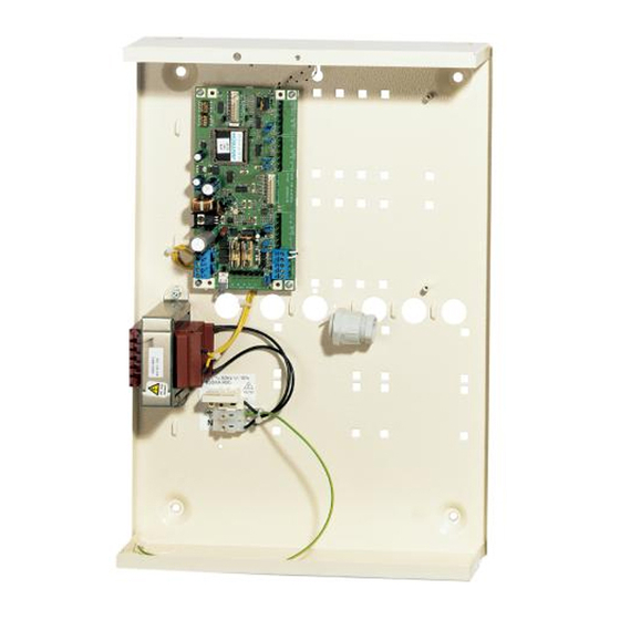
ATS1201 8 to 32 Zone DGP Installation Sheet
EN DA DE ES
FI
FR
1
(1)
( ) 2
(3)
(2)
(4)
3
470 ohm
(1)
(3)
+12V
0V
D+
D-
T
C
(6)
© 2019 UTC Fire & Security Americas Corporation, Inc.
IT
NL NO PL PT SV
(5)
A/R
B/T
Bx/T1
EARTH
Ax/R1
2
(2)
(4)
+12V
0V
D+
D- IN OUT
(7)
+ -
1 / 40
470 ohm
(5)
-
D+
D-
T
C
1 C 2
C 3 C
P/N 1052491 (ML) • REV D • ISS 01JUL19
Advertisement
Table of Contents

Related Manuals for Interlogix ATS1201 8


Summary of Contents for Interlogix ATS1201 8
- Page 1 ATS1201 8 to 32 Zone DGP Installation Sheet EN DA DE ES NL NO PL PT SV ( ) 2 470 ohm 470 ohm +12V D- IN OUT Bx/T1 +12V 1 C 2 C 3 C EARTH Ax/R1 © 2019 UTC Fire & Security Americas Corporation, Inc.
-
Page 2: Mains Power Connection
(10) (11) (12) (13) (13) (14) (15) (16) (17) (20) (18) (19) WARNING: Electrocution hazard. To avoid personal injury or EN: Installation Sheet death from electrocution, remove all sources of power and allow stored energy to discharge before installing or removing equipment. -
Page 3: General Installation Guidelines
To remove a battery: ties to fix the mains cable at the dedicated fixing point provided near the mains terminal connector. Make sure that your product settings allow you to open the cover without starting the tamper alarm. - When installing permanent, fixed wiring, insert an easily accessible, dedicated bipolar circuit breaker in the power Switch off the mains power, if necessary, and remove the distribution network. - Page 4 ATS1201 connections DGP DIP switch settings • Address: Select DGP address. Set switches 1 to 4 to Off Figure 4: ATS1201 connections to disable the DGP. See Figure 2 for correct address (1) 12 V battery. (12) J5: Interface to ATS1202 settings.
-
Page 5: Specifications
End of line resistor (standard) Refer to ATS control panel Contact information installation guide Ext.siren (J7: S+/S−) Standard on board output www.utcfireandsecurity.com or www.interlogix.com Electronic output Rating: 1 A at 13.8 VDC For customer support, see www.utcfssecurityproducts.eu Dimensions metal housing LxWxH 360x260x82 mm Colour... - Page 6 Afbryd Net-forsyningen, hvis dette er nødvendig, samt gør det nemmere at holde orden på kablerne inde i åben kabinettet. kabinettet. • Afbryd akkumulatorerne, fjern ledningerne fra tilslutnings Den akkumulator, der anvendes til denne enhed, skal terminalerne på akkumulatoren. Bemærk, afhængig af være fremstillet af materialer af egnet akkumulator type kan tilslutnings terminaler være placeret brændbarhedsklasse (HB eller bedre).
- Page 7 Skærmen på databuskablet skal tilsluttes til jord på ATS- Jordtilslutning af et kabinet som indeholder flere enheder centralenheden, og må altid kun i den ene ende. Alle printenheder til systemet er monteret med en terminal for Hvis afstanden mellem en RAS (betjeningspanel) og den spadesko, denne har forbindelse til metalkabinettet og kan nærmeste central eller DGP er mere end 100 meter, anbefales anvendes for jord-tilslutning.
- Page 8 Maks. belastning: 1 A ved www.recyclethis.info 13,8 VDC Størrelse metalkabinet LxWxH 360x260x82 mm Kontaktinformation Farve Beige www.utcfireandsecurity.com eller www.interlogix.com. 0 to til +50°C (certified +5 til 40°C) Driftstemperatur For kundesupport se www.utcfssecurityproducts.dk Relativ fugtighed Maks. 95 % ikke kondenserede IP-klasse IP30...
-
Page 9: Montage
bitte die Spezifikationen Ihres Produkts oder kontaktieren Sie - Niemals die Kabelenden der Netzzuleitung durch den technischen Support für weitere Informationen zum Weichlöten verzinnen, wenn diese unter Austausch von Batterien. die Netzanschlussklemme geschraubt/geklemmt werden. • Vermeiden Sie Kabelschleifen innerhalb des Gehäuses und verlegen Sie Kabel so, dass sie nicht auf oder unter Montage den Leiterplatten liegen. - Page 10 Anschlussbelegung ATS1201 Abbildung 3: Verkabelung von ATS1201 mit der Einbruchmeldezentrale ATS Abbildung 4: Anschlussbelegung ATS1201 (1) TERM-Brücke gesteckt (6) Bevorzugter Datenkabeltyp (1) Anschluss für 12 V- (12) J2: RS485-Systemdatenbus (erstes Gerät am lokalen ist WCAT 52 (Verdralltes & Gehäusesabotage- Notstrombatterie. Datenbus).
-
Page 11: Technische Daten
Bestimmungen der Richtlinie 2014/30/EU Kapazität und/oder 2014/35/EU entspricht. Für weitere 12 V nom. (BS131) [2] Informationen siehe www.utcfireandsecurity.com 65 mA bei 13,8 V Gleichspannung ±5% Stromaufnahme der oder www.interlogix.com. Erweiterung P/N 1052491 (ML) • REV D • ISS 01JUL19 11 / 40... - Page 12 El montaje de la batería dentro de la caja sólo es útil para el Kontaktinformationen uso del panel de control en posición estable. Retire la batería www.utcfireandsecurity.com oder www.interlogix.com. para transportar el panel de control. Kontaktinformationen für den Kundendienst finden Sie unter Asegúrese además de que los terminales de cable están...
- Page 13 Conexión del ATS1201 con el Panel de Se recomienda utilizar bridas para cables a fin de mejorar el orden del cableado dentro de la caja. control ATS • La batería utilizada con esta unidad deberá estar El bus de datos del sistema se utiliza para conectar los fabricada con materiales de índice de inflamabilidad paneles expansores de datos (a fin de ofrecer zonas adecuado (HB o superior).
-
Page 14: Puesta A Tierra
ATS1821 (tarjeta de 8 salidas de colector abierto) está Figura 5: Blindaje conectado a J8. (1) Edificio 1 (6) Panel de control de ATS OFF: No hay ninguna tarjeta ATS1811, ATS1820 o (2) Edificio 2 (7) Bus de datos del sistema ATS1821 conectada a J8. -
Page 15: Información De Contacto
Johtojen liittimet tulee erottaa. Mahdollisesti rikkoutuvien johtojen joutuminen kosketukseen toisten johtojen tai Información de contacto virtapiirien kanssa voidaan estää käyttämällä nippusiteitä. www.utcfireandsecurity.com o www.interlogix.com Yleisiä asennusohjeita Para acceder al servicio técnico, consulte www.utcfssecurityproducts.es ATS1201 on valmistettu, asennettu ja testattu siten, että se vastaa tämänhetkisten standardien mukaisia turvallisuus-,... - Page 16 • Jos kotelon ylä- ja/tai alaosan kaapelien läpivientejä ATS1201-kytkentäkaavio käytetään laitteen johdotukseen, on aina käytettävä sopivia läpivientitarvikkeita. Tähän tarkoitukseen saa Kuva 4: ATS1201-kytkentäkaavio käyttää vain sopivan tulenarkuusluokan materiaaleja (11) TERM: Dataväylän pääte. (1) 12 V:n akku. (vähintään HB). (2) Järjestelmän maa. Käytetään vain paikallisen (3) Vaihtojänniteliitäntä...
- Page 17 Lisätietoja: “Maadoitus” alla. dataväyläkaapeli on kytketty vähintään kahden muovikoteloisen laitteen kautta, tulo- ja lähtökaapelin vaipan täytyy olla kytkettynä yhteen. Keskittimen DIP-kytkimien asetukset Kuva 5: Vaippa • Osoite: Käytetään keskittimen osoitteen valitsemiseen. (5) Verkkosyötön liitin (1) Rakennus 1 Keskitin poistetaan käytöstä määrittämällä kytkinten 1–4 (2) Rakennus 2 (6) ATS-keskuslaite asennoksi OFF.
- Page 18 L’emplacement de montage de la batterie est pour un usage Yhteystiedot fixe. Retirer la batterie en cas de transport de la centrale. www.utcfireandsecurity.com tai www.interlogix.com Bien attacher les câbles dans la centrale pour éviter les court- circuits en cas de rupture d’un câble.
- Page 19 • Si les entrées de câbles supérieures ou inférieures sont Connexions ATS1201 utilisées pour passer des câbles, utiliser des presses étoupes adaptés et conformes à la classe de flammabilité Figure 4: Connexions ATS1201 HB minimum. (1) Batterie 12 V. (12) J5 : Connecteur vers les (2) Terre du système extensions d’entrée •...
-
Page 20: Spécifications Techniques
Raccordement à la terre de coffrets dans un même Figure 3: Câblage ATS1201 avec les centrales bâtiment (6) Type de câble de données (1) Cavalier TERM installé Les équipements d'un même bâtiment seront (premier module d’un bus recommandé : WCAT 52 systématiquement raccordés à... -
Page 21: Informations Réglementaires
Prevedere uno spazio libero di 50 mm tra i contenitori degli apparati montati uno a fianco dell'altro e 25 mm tra i contenitori Contact e lo spazio laterale. www.utcfireandsecurity.com ou www.interlogix.com P/N 1052491 (ML) • REV D • ISS 01JUL19 21 / 40... - Page 22 L’alloggiamento per la batteria previsto è indicato per un - Inserire un diodo si soppressione (ad esempio, il tipo utilizzo statico dell’unità di controllo. Togliere la batteria dal 1N4001) a protezione della bobina del relè. contenitore della centrale in caso di trasporto. - Utilizzare esclusivamente relè...
-
Page 23: Messa A Terra
Stazioni di inserimento alla centrale ATS. I dispositivi remoti possono essere distanti fino a 1,5 km dalle centrali ATS. • Tx: il LED rosso lampeggia quando il concentratore (DGP) Le stazioni di inserimento e i concentratori devono essere sta rispondendo al polling eseguito dalla centrale ATS sul collegati alla connessione del bus di dati di sistema tramite bus dati di sistema. - Page 24 Colore Beige Contatto per informazioni 0° — +50 °C (certificato IMQ +5° — Temperatura di funzionamento +40°C) www.utcfireandsecurity.com o www.interlogix.com Umidità relativa 95% max. senza condensa Per l'assistenza clienti, vedere www.utcfssecurityproducts.it Grado di protezione IP IP30 Certificato IMQ II° livello con kit antirimozione ST580...
- Page 25 • alleen uitgevoerd worden door een gekwalificeerde installateur Houd een duidelijke scheiding aan tussen laagspanning- omdat dit invloed kan hebben op de configuratie instellingen en netspanningkabels. Gebruik gescheiden kabelinvoeren van het product, of een alarm kan veroorzaken. van het controlepaneel •...
- Page 26 Aansluitschema ATS1201 Figuur 3: Bekabeling ATS1201 naar ATS (1) TERM-aansluiting (eerste (5) Een willekeurige DI, Figuur 4: Aansluitschema ATS1201 apparaat op lokale gelijkwaardig aan ATS1201, (1) 12 V accu. (11) TERM: Afsluiting van de databus). ATS1210, ATS1220. (2) Systeem-aarding. data bus. Alleen gebruiken (2) TERM-aansluiting (6) Aanbevolen datakabeltype: (3) AC-aansluiting van...
-
Page 27: Technische Specificaties
Als voorbeeld is een BS131 genomen. www.recyclethis.info Algemene specificaties Contact informatie Eindelijnsweerstand (standaard) Zie de installatiehandleiding www.utcfireandsecurity.com of www.interlogix.com van het ATS-controlepaneel Ext.sirene (J7: S+/S−) Voor klantenondersteuning, zie www.utcfssecurityproducts.nl Standaard uitgangen op de print O.C. uitgang Maximaal: 1 A bij 13,8 VDC... - Page 28 Generell installasjonsveiledning NO: Installasjonsveiledning Sentralapparatet ATS1201 er designet, montert og testet på en slik måte at det skal tilfredsstille alle krav til sikkerhet, stråling og immunitet mot elektromagnetisk interferens ifølge gjeldende Strømkontakt for nettilkobling standarder. Bruk nettilkoblingsterminalene til å koble til Hvis retningslinjene nedenfor følges, vil systemet kunne nettstrømforsyningen.
- Page 29 Tilfredsstillelse av kravene til nivå 2 av CEI 79-2, krever at du Figur 3: Kabling ATS1201 med betjeningspanel ATS bruker beskyttelse mot bortbrytningssabotasje (ST580 eller (1) TERM-linken er montert (6) Foretrukket type datakabel ST590-settet). Merk: Avbrytningssabotasjen er ikke inkludert (første enheten på er WCAT 52 (2-pars med produktet.
- Page 30 BS131. www.recyclethis.info Generelle funksjonsspesifikasjoner Kontaktinformasjon Endemotstander: (standard) Se i ATS betjeningspanelets installasjonsmanual www.utcfireandsecurity.com eller www.interlogix.com. Standard påmonterte utganger Ekstern sirene (J7: S+/S−) For kundestøtte, se www.utcfssecurityproducts.no Elektronisk utgang Merkeverdi: 1 A ved 13,8 VDC Dimensjoner metal kabinet 360x260x82 mm...
- Page 31 alarmowej należy więc wyjąć baterie akumulatorowe na czas PL: Instrukcja Instalacji transportu centrali. Należy zwrócić również uwagę na zamocowanie przewodów tak, aby w razie przerwania nie doprowadziły do Podłączenie zasilania sieciowego przypadkowego zetknięcia z innymi przewodami lub obwodem elektronicznym. Sieć elektryczną należy podłączyć do złącza sieciowego. Można w tym celu wykorzystać...
- Page 32 - Stycznik przełączający zasilenie z sieci energetycznej Stacje zazbrajania i moduły zbierania danych muszą być połączone z magistralą systemową za pomocą ekranowanych powinien znajdować się na zewnątrz obudowy centrali przewodów typu 2 pary skręcone (zalecane są przewody alarmowej. WCAT52). - Zawsze podłączaj diodę zabezpieczającą (np. 1N4001) równolegle do cewki przekaźnika.
- Page 33 LEDy Dane techniczne • Tx: Żółta dioda LED błyska, kiedy urządzenie odpowiada Zasilanie z sieci energetycznej na odpytywanie centrali alarmowej. 230 VAC 10%, 50 Hz 10% Napięcie sieci energetycznej (J3: AC) • Rx: Czerwona dioda LED błyska, kiedy centrala odpytuje Pobór prądu przy napięciu 230 V~ 225 mA urządzenie.
- Page 34 Informacje kontaktowe O espaço para a instalação da bateria dentro da caixa só é útil www.utcfireandsecurity.com lub www.interlogix.com. para uma utilização constante do painel de controlo. Retire a bateria para transportar o painel de controlo. Informacje na temat pomocy technicznej można znaleźć na stronie www.utcfssecurityproducts.pl...
- Page 35 Diagrama de ligações ATS1201 • Ao utilizarem os orifícios superiores e/ou inferiores de entrada de cabos no armário para orientar a ligação até Figura 4: Diagrama de ligações ATS1201 ao painel de controlo, utilize sempre um processo de colocação de tubos através de uma conduta e caixa de (1) Bateria de 12 V.
-
Page 36: Especificações Técnicas
Esta ligaçã à terra tem de ser verificada por um fornecedor Figura 3: Ligação ATS1201 com o painel de controlo autorizado. (1) Ligação TERM colocado (6) O tipo de cabo de dados preferencial é o WCAT 52 (primeiro dispositivo no Ligar à... - Page 37 Informação de contacto Allmänna riktlinjer för installationen www.utcfireandsecurity.com ou www.interlogix.com ATS1201 har konstruerats, tillverkats och testats för att uppfylla aktuella standarders krav avseende säkerhet och P/N 1052491 (ML) • REV D • ISS 01JUL19...
- Page 38 emissioner med hänsyn till elektrisk och elektromagnetisk Mer information om kretskortet finns i “Kopplingsschema interferens med omgivningen. ATS1201” nedan. Om de följande riktlinjerna efterlevs kommer systemet att ge många år av pålitlig funktion. Kopplingsschema ATS1201 Utöver följande riktlinjer är det viktigt att följa alla lokala och Figur 4: Kopplingsschema ATS1201 tillämpliga standarder vid installation av ATS1201.
- Page 39 Jordningscentraler i flera byggnader Figur 3: Anslutning av ATS1201 till centralapparat ATS Om kablaget sträcker ut sig till flera separata byggnader måste (1) ”TERM”-bygeln monterad (6) Datakabel som mer än ett gemensamt jordsystem användas. Använd (första enheten på lokal rekommenderas är frånskiljare/repeater ATS1740 för att isolera databuss).
- Page 40 återförsäljare vid köp av liknande ny utrustning eller lämnas till en därför avsedd deponering. För mer information, se: www.recyclethis.info Kontaktuppgifter www.utcfireandsecurity.com eller www.interlogix.com Kundsupport finns på www.utcfssecurityproducts.se P/N 1052491 (ML) • REV D • ISS 01JUL19 40 / 40...