Table of Contents
Advertisement
Quick Links
TruPortal
Dual Door
™
Interface Module
Quick Reference
en-US
Introduction
The TruPortal Dual Door Interface Module (TP-ADD-2D) can
support two complete door configurations, with up to two readers
per door. This module provides termination points for door
contacts (door position switches) and Request to Exit (RTE)
devices, as well as two door strike relays to control power to the
controlled access doors. It communicates with the TruPortal
System Controller (TP-SYS) via a two-wire RS-485 SNAPP bus.
Model Numbers
The TruPortal Dual Door Interface Module is available in a board-
only configuration (TP-ADD-2D-BRD) (see
installed in a UL or CE enclosure with or without bundled readers
and credentials (TP-ADD-2DR, TP-ADD-2D).
The TruPortal Dual Door Interface Module is available in the
following configurations:
•
TP-ADD-2D-BRD (board only)
•
TP-ADD-2D (installed in UL enclosure)
•
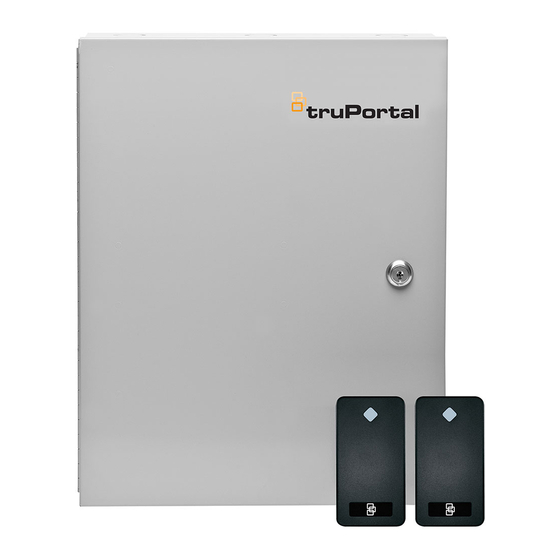
TP-ADD-2D2R (installed in UL enclosure with two readers)
•
TP-ADD-2D-E (installed in CE enclosure)
•
TP-ADD-4D (installed in UL enclosure with two Dual Door
Interface Modules)
Note:
-E model numbers are "Not Evaluated by UL" and
therefore cannot be used in UL installations.
P/N 460802001C • REV 01.00 • 25JUL13
Packing List
•
•
•
•
•
Installation Procedure
To install the TruPortal Dual Door Interface Module, perform the
procedures described in the following sections, in the order in
which they are presented.
1.
2.
3.
4.
5.
6.
Figure
9) or pre-
7.
8.
9.
10. Ensure all wires are clear and secure the cover.
WARNING: Circuit board components are vulnerable to damage
TruPortal Dual Door Interface Module (quantity = 1)
Mounting plate (depending on option ordered)
UL or CE enclosure with power supply (depending on option
ordered)
T-100 readers (depending on option ordered; quantity = 2)
Installation kit which includes:
-
Two positional terminal plug-in block (quantity = 5)
-
Three positional terminal plug-in block (quantity = 4)
-
Four positional terminal plug-in block (quantity = 4)
-
Six positional terminal plug-in block (quantity = 2)
-
1N4005 diodes (quantity = 2)
-
End-of-Line (EOL) resistors 1k ohm, 1% (quantity = 8)
-
Plastic board supports for optional mounting
(quantity = 4)
Mount the enclosure.
Mount the module in the enclosure.
Wire the relay outputs for door strike(s) and AUX.
Wire the reader(s).
Install the reader voltage jumpers.
Wire the alarm inputs.
Wire the tamper switch.
Wire the power and communications inputs
Apply power to the unit and listen for the relays to click.
Observe LED indicators to verify correct board operation.
by electrostatic discharge (ESD). ESD can cause
immediate or subtle damage to sensitive electronic
parts. An electrostatic charge can build up on the
human body and then discharge when touching a
board. A discharge can be produced when walking
across a carpet and touching a board, for example.
Before handling any board, make sure to dissipate
any charge by touching the ground. This discharges
any static electricity build-up.
1
Advertisement
Table of Contents

Summary of Contents for Interlogix TruPortal TP-ADD-2D-BRD
- Page 1 TruPortal Dual Door ™ Interface Module Quick Reference en-US Packing List • TruPortal Dual Door Interface Module (quantity = 1) • Mounting plate (depending on option ordered) • UL or CE enclosure with power supply (depending on option ordered) • T-100 readers (depending on option ordered;...
- Page 2 Mounting the Enclosure Figure 1: Components and Cable Specifications Remove enclosure from shipping container and remove any packing material. Using the template provided (part number 531119001 or 531120001), mark and then drill mounting holes. To mount on dry wall, use 1/8 in. (3.175 mm) hollow wall, expansion anchors.
-
Page 3: Table Of Contents
Output Wiring Magnetic Locks and Other “Fail-Safe” Door Locks The contact protection circuit must be used. The two circuits The default door lock wiring is for “Fail Secure” (powered = shown in Figure 2 Figure 3 are recommended. Locate the unlocked). -
Page 4: Callout Description
Reader Voltage Jumpers Communications (SNAPP Bus) and Power Wiring For reader power (data line pull-up) voltage selection, refer to the Communication ports TB1 and TB6 are two-wire RS-485 interfaces used to connect RS-485 from the System Controller following table and Figure (TP-SYS) to additional input/output (I/O) modules downstream. -
Page 5: Reader
Figure 9: Dual Door Interface Module +12V +12V GND RTMP BUZ 5/12 GRN RED/ COM1 COM2 DCNT R1D1 R1D0 R2D1 R2D0 Table 1: Dual Door Interface Module Pinouts Terminal Block Pin Label Description Callout Description Callout Description +12V (+) 12 V - Red TB1 (Module Bus;... -
Page 6: Black
Terminal Block Pin Label Description Aux Input COM/Shared Request to Exit Normally Open COM1 Aux Relay Normally Closed COM2 Common Normally Open +12V (+) 12V - Red Data A - Green Data B - Yellow (-) 0V - Black Normally Open COM1 Aux Relay Normally Closed... - Page 7 Figure 10: TP-ADD-2D Enclosure Dimensions Figure 11: TP-ADD-4D Enclosure Dimensions Callout Description Callout Description Front view; cover not shown Front view; cover not shown Bottom view; top view the same Bottom view; top view the same Side view typical Side view typical 0.20 in.
- Page 8 Figure 12: Mounting in AL400 Enclosure with Mounting Plate Figure 13: Mounting in AL600 Enclosure with Mounting Plate Callout Description Callout Description TP-ADD-2D TP-ADD-2D 28058B-02 mounting plate 28058B-02 mounting plate TP-ADD (AL600) enclosure TP-ADD (AL400) enclosure #6-32 SEMS nut, 8 holes #6-32 SEMS nut, 8 holes #6-32 x .38 in.
- Page 9 Figure 14: Mounting in AL400 Enclosure without Mounting Plate Figure 15: Mounting in AL600 Enclosure without Mounting Plate Callout Description Callout Description TP-ADD-2D TP-ADD-2D TP-ADD (AL600) enclosure TP-ADD (AL400) enclosure #6-32 x 1.00 in. (25.4 mm) plastic standoff, 4 holes #6-32 x 1.00 in.
- Page 10 Customer support: www.interlogix.com/support © 25JUL13 United Technologies Corporation Interlogix is part of UTC Climate Controls & Security, a unit of United Technologies Corporation. All rights reserved. Document number: 460802001C - July 2013 TruPortal Dual Door Interface Module Quick Reference...


