
Related Manuals for Horizon Fitness H-1000XP


Summary of Contents for Horizon Fitness H-1000XP
- Page 1 User Manual H-1000XP Fuel Cell System Date:2013-08-05 Part Number:H-1000XP Version:20130805...
- Page 2 Revision History Release No. Date Revised by Revision Description Rev. 0 12/13/10 Tony User’s Manual draft Rev. 0.9 12/24/10 1. Modified PART LIST 2. Modified GENERAL INFO 3. Modified SYSTEM SET UP 4. Modified SOFTWARE 5. Added MAINTENENCE Rev. 0.95 01/13/11 1.
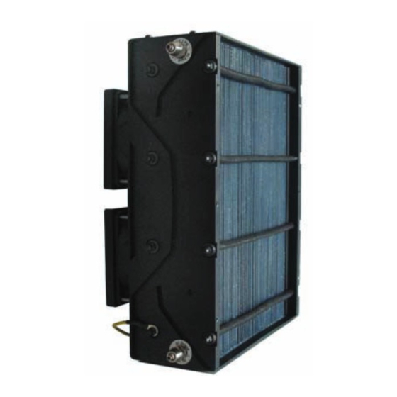
- Page 3 Thank you for choosing our fuel cell stack. The Horizon fuel cell stack is an air-cooled, light weight and compact fuel cell stack. H-1000XP is specially developed for SHELL Eco-marathon event,(please refer to www.shell.com/ecomarathon/ for more details), this system has been designed...
-
Page 4: Table Of Contents
Table of Content Safety…………………………………………………………6 Part list………………………………………………………12 General information…………………….……….…………18 System set up……………………………………………….27 Software …………………………………………………….42 Maintenance………………………………………….….….47 Troubleshooting ……………………………………….……50... - Page 5 Terminology PEM fuel cell: A PEM (Proton Exchange Membrane) fuel cell is a device that converts hydrogen and oxygen into water and electricity. A fuel cell stack: It includes a plurality of plate-like fuel cells arranged along an axis generally parallel to cell thickness with electrically conductive separator plates between each pair of cells.
-
Page 6: Safety
1.0 SAFETY 6 ... - Page 7 Possible situations include low cell voltage, high current, high temperature, or hydrogen leak detection. • Do not dismantle the H-1000XP system. Contact HORIZON if you have any concerns about operation. 1.2 Using Hydrogen WARNING! FIRE OR EXPLOSION Keep all sources of ignition away from hydrogen.
- Page 8 Hydrogen embrittlement can lead to leakage or catastrophic failures in metal and non-metallic components. As a preventative measure, H-1000XP must be operated in a well-ventilated area in order to inhibit potential hydrogen accumulation.
- Page 9 WARNING! Keep all sources of ignition away. Smoking is not permitted in the vicinity of the H-1000XP 1.6 Oxygen Depletion Oxygen is a colorless, odorless, non-toxic and tasteless gas. Oxygen is essential for life in appropriate concentrations.
- Page 10 H-1000XP. Never use damaged extension cords. Minimize conductivity by avoiding surfaces in contact with water; hands and clothes must be dry. Do not operate or store H-1000XP in wet or damp conditions.
- Page 11 WARNING! Minimize static discharge. Ground all equipment. Residual reactants within the H-1000XP can develop a charge in a matter of minutes when turned off. A reading of zero volts across the entire power module does not guarantee that all fuel cells are uncharged.
-
Page 12: Part List
2.0 PART LIST 12 ... - Page 13 2.0 PART LIST 1. Stack The H-1000XP fuel cell stack is a cathode-cooled proton exchange membrane (PEM) fuel cell stack designed to provide stable electrical power while operating on air and dry hydrogen. With innovative materials, the H-1000XP achieved 1000W power output with more efficiency comparing to standard H1000.
- Page 14 5. SCU switch It is to turn the SCU on/off. For SCU, Please refer to Terminology. 6. LCD display It displays the system status, current, voltage, temperature etc. Please refer to trouble shooting section for more details 7. Hydrogen sensor (Optional) It triggers at 25% of LFL, which is 1% hydrogen concentration.
- Page 15 9. Ambient temperature sensor It senses the ambient temperature. The sensor should be place opposite to the blower side of the fuel cell stack. As is showed in system set up section. 10. DC/DC converter (Optional) The DC/DC will regulate the output voltage for the controller.
- Page 16 Status LED LCD display socket It controls the stack and all peripheral parts to perform at its 13. System controller optimal condition. It has the following features Control Stack temperature Control Stack purge rate Monitoring stack current and voltage Monitoring H2 concentration(H2 sensor needed) Protect stack from possible failures, like stack low voltage, over current, over temperature Control Hydrogen supply and shut off...
- Page 17 Controller Signal Connector from Controller box at the wire side: Wire colors Connector pin # Peripherals controlled Red #1 & #2 Stack Temperature Sensor Grey #3 & #4 Ambient Temperature Sensor Red & Black #5 & #6 Blowers (Red #5= +ve, Black #6= ‐ve) Black #7 & #8 Hydrogen Purge Valve (Black #7= +ve, Black #8= ‐ve) Yellow #9 & #10 Hydrogen Supply Valve (Yellow #9= +ve, Yellow #10= ‐ve) Blue #11 & #12 Short Circuit Switch Red & Black #13 & #14 N/A Black #15 N/A Black #16 Blower PWM Table 2.1 Controller Connector ...
-
Page 18: General Information
3.0 GENERAL INFORMATION 18 ... - Page 19 3.0 GENERAL INFORMATION 3.1 Dimensions 3.0 GENERAL INFORMATION Figure 3.1.1 Views and dimensions of H-1000XP stack Figure3.1.2 Views and dimensions of controller...
- Page 20 Fuel Hydrogen consumption 12.5SLPM @1000W or flowrate External temperature 5 - 35°C ° 5 Humidification Self-humidified operation n i l Relative humidity 10%-95%RH non-condensing Monitoring RS232 System status / Historical data Chart 3.2 General Specifica on of H-1000XP...
- Page 21 3.3 Electric Circuit Diagram Figure 3.3 Electric Circuit Diagram for H-1000XP Please refer to section 2.0 for more details of each part...
- Page 22 3.4 H-1000XP Performance Specifications The H-1000XP can deliver up to 33A of current. Its operating voltage ranges from 46V (no load) to 30V (full load). The rated operating point of 33A@30V is recommended. NOTE: All the performances are under lab condition.
- Page 23 Please store the stack in an airtight container when not in use. 3.4.3 Peak power output The H-1000XP can deliver a peak power output of 1200W* to meet the high power requirements during vehicle climbing hills. This is realized by connecting an ultra capacitor in parallel hybrid configuration.
- Page 24 3.4.4 System hydrogen consumption rate Figure 3.4.4 presents the fuel consumption rate of the H-1000XP system at different power outputs. The data is recorded in Nominal operating conditions (please refer to 3.4.1 for more details) Please NOTE the fuel consumption will also vary with ambient temperature, since...
- Page 25 3.4.5 Airflow requirements Fuel cell system requires airflow for reaction oxidant as well as cooling. Figure 3.4.5 below shows the estimated airflow requirements of the H-1000XP at different power outputs. Slight contaminant level in the operating environment has insignificant effect on the H-1000XP performance over the full product lifetime.
- Page 26 3.5 Control and Communication Communication channel: RS232 serial byte format, 9600 bps, 8 data bits, no parity, 1 stop bit; Little-endian format. Message frequency: 1k Hz. Reportable parameters: Name Data Range Resolution Baud rate Frequency(Hz) Fuel Cell Stack Voltage 25‐50V 0.3V 9600 1k Fuel Cell Stack Current ...
-
Page 27: System Set Up
4.0 SYSTEM SET UP 27 ... - Page 28 ● 12VDC Start up power source ● Hydrogen source(operating pressure: 0.5bar / flow rate: 15SL/MIN ) H-1000XP is a self-sustainable system once it is started, to start up the system, a 12V power source is required, and it could be a battery (current above 4Ampere) or a 12VDC power supply with current above 4Ampere please follow the steps carefully to set up the system,please DOT NOT feed...
- Page 29 Step 2 Please place the stack in vertical like this. Then connect the gas line finished in step 1 to stack hydrogen inlet port, as showed in fig 4.3. WARNING! Do not place anything in front of or back from the stack, which may block off the air flow.
- Page 30 Supply valve To H1000XP From hydrogen canister Purge valve To atmosphere From H1000XP Figure 4.6 Figure 4.7 Figure 4.8 Please keep the Please avoid positioning the purge valve near the air hydrogen purge line inlet side. Always position away from the stack, it is the purge valve on the recommended that keep blow side of the stack.
- Page 31 4.2 Setup controller Step 5 Connect control signal connector to the stack, as showed in fig 4.9 Figure 4.9 Step 6 Connect power cord connector to the stack, as showed in fig 4.10 Figure 4.10 31 ...
- Page 32 Step 7 Connect ultra capacitor connector to the ultra capacitor bank, as showed in fig 4.11 A fuse is to be installed on the positive side of the capacitor bank (not provided). This fuse rating will varies from team to team and must be according the Chapter 1 Shell Eco Marathon Rules.
- Page 33 Step 9 Connect hydrogen sensor to the hydrogen sensor connector, as showed in fig 4.13 Please note that some application will not require this component and system will still work without this part Figure 4.13...
- Page 34 Step 10 Connect LCD display to the controller LCD connector; please note system could run without this part, as showed in fig 4.14 Figure 4.14 Connect the hydrogen sensor to on-board battery to power the safety circuit, as showed in fig 4.15 Figure 4.15...
- Page 35 Step 11 Connect the start up battery (not included in the system); it could be any DC power source with 12VDC, current above 4ampere. First, connect the cable to the start up battery. Then plug the cable connector to the controller, as showed in fig 4.16 Figure 4.16 NOTE: It is NOT suggested to...
- Page 36 Step 12 It is highly recommended to connect rs232 to your computer to record system operation data, as showed in fig 4.18 Please refer to the software section for more details Figure 4.18 Step 13 Please make sure the emergency stop switch is at off position, otherwise the system is unable to start Figure 4.19 ...
- Page 37 Step 13 To turn on: Push the button, as showed Figure 4.20 in fig 4.20 To turn off: Wheel the button till it is up, as showed in fig 4.21 Figure 4.21 37 ...
- Page 38 Figure 4.22 Step 14 Connect the load cable to your load, it is suggested that please do not turn on the load before system start up. NOTE: The clamp is NOT suggested to use for connecting。 Figure 4.23 You may find other tools to make the connection more reliable.
- Page 39 4.3 Ready to start up Step 15 Please find the tube to the Hydrogen supply valve, connect it to the regulator. Then set the regulator value to operating pressure: 0.5bar/15SLPM. NOTE: The type of the regulator used for example may be different from yours.
- Page 40 Step 17 Check all the connections first, including the gas and the electricity. Be sure there is no problem of disconnecting. Now it is ready to start the system by Figure 4.28 long press the button (3 seconds) Come to booting up phase, system beeps for a short moment, flash the blue LED, display "Horizon /Fuel Cell"...
- Page 41 Step 17 If the red LED flashing with the beeps, the system comes to the error protection status. For example, the LCD displays “SYSTEM OFF FOR: FCVOLTAGE LOW” means the stack open circuit voltage is too low, and the system will shut off for protection.
-
Page 42: Software
5.0 SOFTWARE 42 ... - Page 43 5.0 SOFTWARE Introduction ECO-Marathon Serial Port Monitor is software, which is developed to help user to communicate with ECO-Marathon system, monitor and record various information, including: Ambient Temperature, Stack Temperature, Stack Voltage, Stack Current, Stack Power, Battery Voltage and Stack Status. 5.1 Features 1.
- Page 44 Usage Open program 1. Find “ECO-Marathon Monitor” in “START\All Programs”. 2. Click the icon to open. Configuration 1. Select I/O Port which is to connect to the ECO-Marathon system. 2. Set Timeout (Default is 100s). 3. Set REC ON/OFF, whether to record data or not. 4.
- Page 45 Curves Panel 1. Ambient Temperature, Stack Temperature, Voltage, Current, Power, Battery Voltage will display as real-time curves on this panel. Figure 5.5 Curves panel History Panel 1. User select the time from the pull down list. Figure 5.6 Pull down list 2. Press the DISPLAY RESULT button, the history data will display in the result records table.
- Page 46 Figure 5.9 History panel 5.5 Error Information 1. Connection Timeout Error Phenomenon A dialogue window will pop up as follow: Figure 5.10 Monitor panel Description ECO-Marathon Serial Port Monitor lost connection to the system. 46 ...
-
Page 47: Maintenance
6.0 MAINTENANCE 47 ... - Page 48 6.0 MAINTENANCE When finished operating the stack, we highly suggest that inject pure water into the stack before place it back in the supplied air tight container to keep the stack from getting too dry. Injecting water into the stack: 1.
- Page 49 WARNING! When you turn off the on/off switch connected to the control box at the temperature of the fuel cell stack higher than 45˚C the stack will not stop working immediately. Only when the stack temperature goes down below 45˚C, the whole system will stop operation in order to protect the stack.
-
Page 50: Troubleshooting
7.0 TROUBLESHOOTING 50 ... - Page 51 7.0 TROUBLESHOOTING LCD, LED and Beep of the status during procedures System Procedure Beep Status Reaction Horizon Green Long Starting up Normal Starting up /Fuel Cell flashing beep System Battery Long Starting up off/Battery voltage is too Shut down flashing beep System off/FC Long Stack voltage Starting up Shut down Voltage flashing...
- Page 52 Rehydrating the fuel cell because the stack cannot reach the rated power 1. Make sure the purging valve is disconnected from the hydrogen outlet connector. 2. Add water to fuel cell through the hydrogen inlet connector, and keep filling until water starts to come out of the hydrogen outlet valve.
- Page 53 Check the SCU 1. During operation with the SCU on, the voltage of the fuel cell will drop. 2. If the fuel cell voltage is not dropping then contact support@horizonfuelcell.com with the diagnostic “SCU not operational” with the controller number. Check the blower controller Before the load is connected, turn on the blower controller Otherwise the load will not run.