Table of Contents
Advertisement
Quick Links
Owner's Operation and Instruction Manual
THIS MANUAL WILL HELP YOU TO OBTAIN EFFICIENT, DEPENDABLE SERVICE FROM THE HEATER, AND ENABLE YOU
TO ORDER REPAIR PARTS CORRECTLY. KEEP IN A SAFE PLACE FOR FUTURE REFERENCE.
SAFETY NOTICE:
If this unit is not properly installed, a fire may result.
For your safety, follow the installation instructions.
Never use make-shift compromises during the
installation of this unit. Contact local building or fire
officials about permits, restrictions and installation
requirements in your area.
CAUTION!
Please read this entire manual before you install or
use this unit. Failure to follow instructions may result
in property damage, bodily injury, or even death.
Improper Installation Could Void Your Warranty!
This product can expose you to chemicals including carbon monoxide, which
is known to the State of California to cause cancer, birth defects and/or other
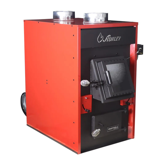
MODEL: AF1500E
Wood Only Central Furnace
SAVE THESE INSTRUCTIONS
Ce produit peut vous exposer à des produits chimiques, y compris le
monoxyde de carbone, qui est connu dans l'État de Californie pour causer
le cancer, des malformations congénitales et / ou d'autres problèmes de
reproduction. Pour plus d'informations, visitez www.P65warnings.ca.gov
CALIFORNIA PROPOSITION 65 WARNING:
reproductive harm. For more information, go to www.P65warnings.ca.gov
United States Stove Company
South Pittsburg, TN 37380
Certified to: UL-391 (R2015) and Certified to: CSA
U.S. ENVIRONMENTAL PROTECTION AGENCY
Certified to comply with the 2016 particulate
emission standards. Not approved for sale after
227 Industrial Park Rd.
Report No. 0215WH055S.REV002
B266.1-11 (R2014)
May 15, 2020
853128B-3705H
Advertisement
Table of Contents

Related Manuals for Ashley AF1500E


Summary of Contents for Ashley AF1500E
- Page 1 Owner’s Operation and Instruction Manual MODEL: AF1500E Wood Only Central Furnace SAVE THESE INSTRUCTIONS THIS MANUAL WILL HELP YOU TO OBTAIN EFFICIENT, DEPENDABLE SERVICE FROM THE HEATER, AND ENABLE YOU TO ORDER REPAIR PARTS CORRECTLY. KEEP IN A SAFE PLACE FOR FUTURE REFERENCE.
- Page 2 CAUTION: • Power source not controlled by furnace main disconnect. • Respect all local and national codes when installing this unit. • This unit is not to be connected to a chimney flue serving another appliance. • This unit is designed to burn solid hardwood only. 57.77 24.14 2.33...
-
Page 3: Specifications
Weight (lbs): 509 lbs. This manual describes the installation and operation of the Ashley, AF1500E wood heater. This heater meets the 2016 U.S. Environmental Protection Agency’s emission limits for wood heaters sold after May 15, 2016. Under specific EPA test conditions this heater has been shown to deliver heat at a rate of 18,850 – 56,000 BTU/hr. This heater achieved a particulate emissions rate of 0.39 lb/mmBtu when tested to method CSA B415.1-10 (*and an... -
Page 4: Tools And Materials Needed For Installation
Safety • WARNING: Do not operate with fuel loading or ash removal doors open. • Do not connect this unit to a chimney flue serving another appliance. • WARNING DANGER: Risk of fire or explosion. Do not burn garbage, gasoline, naphtha, motor oil, or other inappropriate materials. -
Page 5: Installation Options
Furnace Installation INSTALLATION OPTIONS The installation of this furnace includes supplying electrical power, return (fresh air) ductwork, and supply air ductwork. This furnace may be installed in two different configurations. 1. Stand alone wood furnace 2. Add-on wood furnace See kit installation section in this manual to ensure proper assembly, installation and operation of your new furnace. -
Page 6: Duct Work Installation
MAINTENANCE CLEARANCES Your furnace has recommended minimum maintenance clearance requirements. These clearances insure that there is adequate room to preform maintenance and service your furnace. DO NOT store fuel within the specified clearances. See the table and diagram below to determine the clearances for your furnace. -
Page 7: Accessory Installation
CENTRAL INSTALLATION Central Installation Accessory Installation ASSEMBLY OF FURNACE THERMODISC Your furnace requires the following items to be assembled or installed by the service person: Blowers and Blower Controls THERMODISC Electrical Connections COVER 1. Remove all parts from the unit (blowers, thermodisc, and all wiring) and inspect for damage, including the firebrick as some breakage could occur during shipment. -
Page 8: Smoke Curtain
SMOKE CURTAIN Using two 1/4-20 x 1-1/4” Carriage bolts, two smoke curtain clips, and two nuts, attach the smoke curtain in place above the fuel feed door as shown. After installation, the smoke curtain should swing freely back into the furnace. -
Page 9: Electrical Installation
Electrical Installation All electrical connections should be done by a qualified electrician It is recommended to connect the furnace to its own 15 amp 120 Volt circuit from the house power supply 105°C NOTE: Wire leads from the distribution blower are usually BOTH BLACK. - Page 10 Thermostatically Controlled Damper Installation *CANADIAN RESIDENTS ARE REQUIRED TO USE THIS KIT FOR INSTALLATION. STEP 1 STEP 5 Slide the motorized draft actuator into the servo Take off the cover by removing (4) four #10 X 1/2 bracket as shown. screws.
- Page 11 STEP 7 STEP 11 Reattach the cover using the previously removed (4) Route the two red wires included with this kit through four #10 X 1/2 screws. the existing conduit that runs from the junction box up to the T’stat bracket assembly box. STEP 8 Insert the wire into the cable clamp make a loop as shown and then route the wire back through the cable...
- Page 12 STEP 14 STEP 16 Attach the control mounting bracket to the lower Complete all wiring (see “Thermostatically Controlled backside of the unit using (4) four #10 X 1/2 screws. Damper Wiring Diagram” for proper wiring installation). Once the wiring is completed, attach the fan center transformer to the control cover base using (4) four #10 X 1/2 screws.
- Page 13 Thermostatically Controlled Damper Wiring Diagram This kit includes two red wires. Route the two red wires through the existing conduit that runs from the junction box up to the T’stat bracket assembly box. THERMAL DISK INFO: 1. DAMPER ACTUATOR DE-ENERGIZES AND REDUCES BURN SETTING WHEN THE UNIT REACHES TEMPERATURES OF APPROX.
-
Page 14: Air Filter Replacement
Cold Air Return Enclosure Instruction CAUTION: Read all instructions carefully before starting the installation. The cold air return is made up of 4 parts, plus all hardware necessary for assembly. 1. Assemble the fi lter box sides, top, and bottom using sixteen (16) #10x1/2 HX screws. 2. -
Page 15: Chimney Installation
Chimney Installation CHIMNEY Your wood furnace may be hooked up with a factory built or masonry chimney, matching the diameter of the exhaust. If you are using a factory built chimney, it must comply with UL 103 or CSA-B365 standard; therefore it must be a Type HT (2100°F). -
Page 16: Combustible Wall Chimney Connector Pass-Throughs
COMBUSTIBLE WALL CHIMNEY CONNECTOR PASS-THROUGHS Method A. 12” (304.8 mm) Clearance to Combustible Wall Member: Using a minimum thickness 3.5” (89 mm) brick and a 5/8” (15.9 mm) minimum wall thickness clay liner, construct a wall pass-through. The clay liner must conform to ASTM C315 (Standard Specification for Clay Fire Linings) or its equivalent. -
Page 17: Chimney Connector
CHIMNEY CONNECTOR Your chimney connector and chimney must have the same diameter as the furnace outlet. If this is not the case, we recommend you contact your dealer in order to insure there will be no problem with the draft. The furnace pipe must be made of aluminized or cold roll steel with a minimum thickness of 0.021”... -
Page 18: Air Controls
OPERATING THE PRIMARY AND SECONDARY AIR SETTINGS Primary air- is the driving air supply that feeds the fire in the heater. This air is introduced through the damper in the feed door to sustain the combustion. Secondary air – is the air supply that is typically introduced above the fire to effectively “re-burn” the smoke created in the primary combustion before the exhaust gasses exit the stove. -
Page 19: Do Not Burn
Operation The top down method of fire building is recommended for this appliance. After making sure that the stove air intake controls are fully open (open all three air controls to there maximum setting). Place the largest pieces of wood on the bottom, laid in parallel and close together. Smaller pieces are placed in a second layer, crossways to the first. -
Page 20: Testing Your Wood
It is EXTREMELY IMPORTANT that you use DRY WOOD only. The wood should have dried for 9 to 15 months, such that the humidity content (in weight) is reduced below 20% of the weight of the log. It is very important to keep in mind that even if the wood has been cut for one, two or even more years, it is not necessarily dry, if it has been stored in poor conditions. - Page 21 HEATING WITH YOUR WOOD FURNACE 1. Spread the fire and coals evenly towards the center of the combustion chamber before loading your furnace fully or adding more wood. 2. Avoid overfilling the combustion chamber. Air must be allowed to circulate freely through the upper portion of the combustion chamber for the stove to perform best.
-
Page 22: Over Firing
ASH DISPOSAL Whenever ashes get 3 to 4 inches deep in your firebox or ash pan, and when the fire has burned down and cooled, remove excess ashes. Leave an ash bed approximately 1 inch deep on the firebox bottom to help maintain a hot charcoal bed. -
Page 23: Power Failure Instructions
POWER FAILURE INSTRUCTIONS DO NOT add additional fuel after a power failure, remove all air filters and reduce combustion air to a minimum. Observe furnace closely until power is restored. OPERATIONAL TIPS Operational Tips for Good, Efficient, and Clean Combustion •... -
Page 24: Replacement Parts
Replacement Parts Ring, Flue Collar Flue Collar, 6” C.I. Gasket, Flue Collar Stub Collar 8” 22761 40246 88032 891214 Handle Assembly Assembly, Ash Door Ashpan Weldment Wooden Knob Assembly 891098 610496 610498 892767 Cast Grate Curtain, Smoke Shaker Grate Tool Firebrick (4.5 X 9) Pumice 89066 40605... - Page 25 Replacement Parts Control Mounting Bracket T-Disc (200-20°F) Actuator Conduit Assy. Cabinet Back 22140 80789 610850 27883 Cabinet Top Left Cabinet Side Locking Mech, Feed Door Feed Door Hinge Bracket 25562 25467 891097 22662 Hinge Spacer Firebrick 4-1/2 X 7-1/2 Feed Door Assy. Tertiary Damper Assy.
- Page 26 Replacement Parts Wooden Handle Board, Ceraminc Fiber Secondary Tube Brick Retainer 89520 892726 86870 27879 Right Shoulder Front Liner Left Shoulder Blower Gasket 28015 27937 28016 89319 Wire Guide Slide Plate Assembly Blower Assembly Cable Clamp 28746 610750 80594 83785 Back Plate Assembly Cover Weldment Transformer, Fan Center...
- Page 27 Replacement Parts Filter Box, Medium Panel Upper Handle Bracket ADJ. 140°F Thermodisc Left Heat Shield 28708 27924L 80388 28789 Right Heat Shield Right Cabinet Side Servo Bracket Motorized Draft Actuator 28790 28665 28613 80592 ROOM TEMP SET TEMP °F °F SYSTEM HEAT Galvanized Steel Wire...
-
Page 28: Service Record
Service Record It is recommended that your heating system is serviced regularly and that the appropriate Service Interval Record is completed. SERVICE PROVIDER Before completing the appropriate Service Record below, please ensure you have carried out the service as described in the manufacturer’s instructions. Always use the manufacturer's specified spare part when replacement is necessary. - Page 29 Notes -29-...
- Page 30 Notes...
- Page 31 How to order Replacement Parts / Comment commander des pièces de rechange This manual will help you obtain efficient, dependable service from your stove, and enable you to order repair parts correctly. Keep this manual in a safe place for future reference. When writing, always give the full model number which is on the nameplate attached to the stove.