Table of Contents
Advertisement
Quick Links
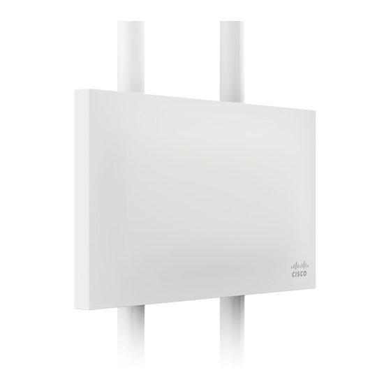
MR72 Installation Guide
The Cisco Meraki MR72 is a dual-band enterprise class 802.11ac cloud-managed access point. Designed for high
capacity and high density, the MR72 meets the needs of the most demanding environments, and also includes the first
ever cloud-managed third radio dedicated to optimizing the RF environment and securing the airwaves.
The Meraki MR72 has an operating temperature of -40o to 60o C.
Package Contents
The MR72 package contains the following:
• MR72 Cloud-Managed Access Point
• Mount cradle
• Wall screws
• Wall screw anchors
• Grounding screws
• Mounting straps
Understanding the MR72
Your Meraki MR72 has the following features:
LED indicator
Your MR72 is equipped with a multi-color LED light on the bottom edge of the unit to convey information about system
functionality and performance:
• Orange - AP is booting (permanent Orange suggests hardware issue)
1
Advertisement
Table of Contents

Related Manuals for Cisco MERAKI MR72


Summary of Contents for Cisco MERAKI MR72
- Page 1 MR72 Installation Guide The Cisco Meraki MR72 is a dual-band enterprise class 802.11ac cloud-managed access point. Designed for high capacity and high density, the MR72 meets the needs of the most demanding environments, and also includes the first ever cloud-managed third radio dedicated to optimizing the RF environment and securing the airwaves.
- Page 2 • Rainbow - AP is initializing/scanning • Blinking Blue - AP is upgrading • Green - AP in Gateway mode with no clients • Blue - AP in Gateway mode with clients • Blinking Orange - AP can't find uplink The MR72 may be operated in “Run Dark”...
- Page 3 The Vent The vent allows pressure equalization between the interior and the environment. This prevents internal condensation and maintains a waterproof seal. The mount cradle has the following features: Mounting posts (4x) The mounting slots located in the middle of the mounting plate marry the MR72 to the mounting plate. Mounting holes (4x) The mounting holes located on the 4 outermost corners of the mounting plate allow secure installation of the mounting plate to a surface such as a wall.
-
Page 4: Pre-Install Preparation
Mount plate attachment screw The mount plate attachment screw is located at the bottom of the mounting plate. It securely attaches the AP to the mounting plate. Mount plate grounding post The mount plate grounding post located on the left side of the mounting plate. Using the included grounding strap, the ground post allows you to ground the unit. -
Page 5: Assigning Ip Addresses To Mr72S
Assigning IP Addresses to MR72s All gateway MR72s (MR72s with Ethernet connections to the LAN) must be assigned routable IP addresses. These IP addresses can be dynamically assigned via DHCP or statically assigned. Dynamic Assignment When using DHCP, the DHCP server should be configured to assign a static IP address for each MAC address belonging to a Meraki AP. -
Page 6: Installation Instructions
Collect Additional Hardware for Installation You will need the following tools to perform an installation: • Network cables with RJ45 connectors long enough for your particular mounting location • 802.3af or 802.3at PoE power source (either PoE switch or Meraki PoE Injector) •... -
Page 7: Remove The Mount Plate From The Access Point
Remove the Mount Plate from the Access Point Before installing the mount plate, you must remove it from the back of the access point. 1. Unscrew the mount plate attachment screw. 2. Lift the mount plate release tab upwards. 3. While holding the mount plate release tab up, slide the mount plate off the access point in the direction shown below. -
Page 8: Mount The Mr72
Mount the MR72 Attach the MR72 to the Mount Cradle Insert the posts on the back of the access point into the attachment slots on the mount plate. Aim Antennas If you are using directional antennas, aim them appropriately to ensure optimal performance for your specific network topography. -
Page 9: Power The Mr72
1. Route the Ethernet cable from the PoE Injector “OUT” port or from a PoE enabled switch to the MR72. 2. Install a Cable Gland on the MR72 end of the cable. 3. Plug the Ethernet cable into the Ethernet port of the Meraki MR72. a. Connect the cable to the Ethernet port on the MR72. -
Page 10: Verify Device Functionality And Test Network Coverage
Powering the MR72 with an 802.3af Power over Ethernet Switch Route Ethernet cable from a port on an active 802.3af PoE switch to the Eth0 port in the bay of the MR72. The MR72 is Gigabit Ethernet-capable. To maximize device performance, a Gigabit-capable switch should be used. Verify Device Functionality and Test Network Coverage 1. -
Page 11: Български (Bulgarian)
The outdoor usage of the 2.4 GHz band requires an authorization from the Electronic Communications Office. 2.4 GHz frekvenču joslas izmantošanai ārpus telpām nepieciešama at auja no Elektronisko sakaru direkcijas. Български (Bulgarian): Настоящото Cisco Systems, Inc. декларира, че това безжичното устройство е в съответствие със съществените изисквания и другите приложими разпоредби на Директива 1999/5/EC. - Page 12 Hereby, Cisco Systems, Inc. declares that this wireless device is in compliance with the essential requirements and other relevant provisions of Directive 1999/5/EC. Español (Spanish): Por medio de la presente Cisco Systems, Inc. declara que el wireless device cumple con los requisitos esenciales y cualesquiera otras disposiciones aplicables o exigibles de la Directiva 1999/5/CE. Ελληνική (Greek): ΜΕ...
- Page 13 Hér, Cisco Systems, Inc. yfir að þráðlaus tæki er í samræmi við grunnkröfur og önnur viðeigandi ákvæði tilskipunar 1999/5/EB. Italiano (Italian): Con la presente Cisco Systems, Inc. dichiara che questo wireless device è conforme ai requisiti essenziali ed alle altre disposizioni pertinenti stabilite dalla direttiva 1999/5/CE. Latviski (Latvian): Ar šo Cisco Systems, Inc.
-
Page 14: Polski (Polish)
Cisco Systems, Inc. declara que este wireless device está conforme com os requisitos essenciais e outras disposições da Directiva 1999/5/CE. Română (Romanian): Prin prezenta, Cisco Systems, Inc. declară că acest dispozitiv fără fir este în conformitate cu cerin?ele esen?iale ?i alte prevederi relevante ale Directivei 1999/5/CE. Slovensko (Slovenian): Cisco Systems, Inc. -
Page 15: Eu Radiation Exposure Statement
• Consult the dealer or an experienced radio/TV technician for help. FCC Caution Any changes or modifications not expressly approved by Cisco Systems, Inc. could void the user’s authority to operate this equipment. This Transmitter must not be co-located or operation in conjunction with any other antenna or transmitter. -
Page 16: Canadian Regulatory Wireless Notice
FCC Registration Requirement Section 15.407 of the FCC rules establishes filing requirements for U-NII operators that deploy a collection of more than 1000 outdoor access points operating in the 5.15-5.25 GHz band. Such operators must submit a letter to the FCC lab acknowledging that, should harmful interference to licensed services in this band occur, they will be required to take corrective action. -
Page 17: Australia Radiation Exposure Statement
(ii) De plus, les utilisateurs devraient aussi être avisés que les utilisateurs de radars de haute puissance sont désignés utilisateurs principaux (c.-à-d., qu’ils ont la priorité) pour les bandes 5250-5350 MHz et 5650-5850 MHz et que ces radars pourraient causer du brouillage et/ou des dommages aux dispositifs LAN-EL. Industry Canada Radiation Exposure Statement This equipment complies with IC radiation exposure limits set forth for an uncontrolled environment. -
Page 18: Taiwan Wireless Statements
or television receiver in a domestic environment, it may cause radio interference. Install and use the equipment according to the instruction manual. Taiwan Wireless Statements 低功率射頻設備的管理辦法 第12條 經型式認證合格之低功率射頻電機, 非經許可,公司、商號或使用者均不得 擅自變更頻率、加大功率或變更原設計 之特性及功能。 第14條 低功率射頻電機之使用不得影響飛航安 全及干擾合法通信;經發現有干擾現象 時,應立即停用,並改善至無干擾時方 得繼續使用。 前項合法通信,指依電信法規定作業之 無線電通信。 低功率射頻電機須忍受合法通信或工 業、科學及醫療用電波輻射性電機設 備之干擾。... -
Page 19: Brazil Wireless Statement
Article 14: The operation of the low-power radio-frequency devices is subject to the conditions that no harmful interference is caused to aviation safety and authorized radio station; and if interference is caused, the user must stop operating the device immediately and can’t re-operate it until the harmful interference is clear. The authorized radio station means a radio-communication service operating in accordance with the Communication Act.