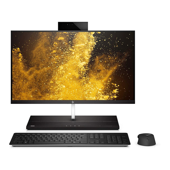
HP EliteOne 1000 G2 Hardware Reference Manual
All-in-one business pcs
Hide thumbs
Also See for EliteOne 1000 G2:
- Disassembly instructions (5 pages) ,
- Disassembly instructions manual (9 pages)
Table of Contents
Advertisement
Quick Links
Advertisement
Table of Contents

Related Manuals for HP EliteOne 1000 G2


Summary of Contents for HP EliteOne 1000 G2
- Page 1 Hardware Reference Guide HP EliteOne 1000 G2 All-in-One Business PCs...
- Page 2 U.S. and/or other countries. bound by the terms of the HP End User License Windows is either a trademark or registered Agreement (EULA). If you do not accept these...
- Page 3 About This Book This guide provides basic information for upgrading this computer model. WARNING! Indicates a hazardous situation that, if not avoided, could result in death or serious injury. CAUTION: Indicates a hazardous situation that, if not avoided, could result in minor or moderate injury. IMPORTANT: Indicates information considered important but not hazard-related (for example, messages related to property damage).
- Page 4 About This Book...
-
Page 5: Table Of Contents
Table of contents 1 Product features ............................1 Overview ................................1 Base unit top components ............................. 1 Base unit side components ........................... 2 Base unit rear components ............................ 2 Monitor front components (select products only) ....................3 Webcam components ............................3 Infrared (IR) webcam (optional) ...................... - Page 6 Replacing or installing a webcam ........................28 Appendix A Electrostatic discharge ........................31 Preventing electrostatic damage ........................31 Grounding methods ............................. 31 Appendix B Computer operating guidelines, routine care, and shipping preparation ..........32 Computer operating guidelines and routine care ....................32 Shipping preparation ............................
-
Page 7: Product Features
Product features Overview NOTE: For the latest manuals on this product, go to http://www.hp.com/support. Select Find your product, and then follow the on-screen instructions. Base unit top components Components Power button End call button Call button Speaker mute button Microphone mute button... -
Page 8: Base Unit Side Components
Base unit side components Components Fingerprint reader USB Type-C Thunderbolt™ port with HP Sleep and Charge Audio-out (headphone)/Audio-in USB SuperSpeed port with HP Sleep and (microphone) combo jack Charge Base unit rear components Components USB SuperSpeed Plus ports (4) Power connector... -
Page 9: Monitor Front Components (Select Products Only)
Monitor front components (select products only) Components Webcam On-screen display buttons (for adjusting the screen) Webcam components Infrared (IR) webcam (optional) Components Front View Webcam light IR webcam IR light Rear webcam adjustment wheel Full High Definition (FHD) webcam Top view Digital microphones Rear view Webcam light... -
Page 10: Full High Definition (Fhd) Webcam (Optional)
Full High Definition (FHD) webcam (optional) Components Front view Webcam light FHD webcam Top view Digital microphones Serial and product number locations Each computer has a unique serial number and product ID number that are located on the exterior of the device. -
Page 11: Setup
Setup Installing the monitor head A monitor head can be installed in the standalone computer base. The monitor head can then be removed and replaced with a different monitor. Remove all removable media, such as USB flash drives, from the computer. Turn off the computer properly through the operating system, and turn off any external devices. - Page 12 Disconnect the two monitor cables attached to the system board by squeezing firmly inward on the two ends of the cable connectors (1) and pulling the cable connectors up and off the system board (2). To remove the rear access cover from the computer, press the two release buttons on the rear of the base unit (1), and at the same time rotate the rear of the cover up (2).
- Page 13 Loosen the two captive screws at the base of the monitor head’s neck (1). While holding onto the bottom of the monitor head from the front with one hand, slide the monitor head back with your other hand to clear it from the small metal retention tab, and then lift the monitor off the base (2). IMPORTANT: The monitor head is heavy.
-
Page 14: Connecting The Power Supply
Connect the two monitor cables to the system board connectors. To replace the rear access cover, slide the tabs on the front of the rear cover into the slots on the rear of the front cover (1), and then press the rear of the rear cover down (2). NOTE: Be sure that all cables are properly routed to prevent damage when the cover is replaced. -
Page 15: Enabling The Monitor Head Detection Warning
Enabling the monitor head detection warning This warning is monitored if the monitor head cables are not fully connected. HP recommends ensuring that this warning is enabled on systems with an installed monitor head. Turn on or restart the computer, and when the HP logo appears, press to enter Computer Setup. -
Page 16: Adjusting The Monitor Head Position
Adjusting the monitor head position Tilt the monitor head to set it to a comfortable eye level. NOTE: The 23.8-inch, 27-inch, and 34-inch monitor heads tilt back. Only the 23.8-inch and 27-inch monitor heads tilt forward. The 34-inch monitor head does not tilt forward. Adjust the height of the monitor head to set it to a comfortable eye level. -
Page 17: Connecting A Secondary Monitor
DisplayPort or HDMI port, you can purchase a video adaptor from HP for your configuration. DisplayPort adapters, HDMI adapters, and video cables are purchased separately. HP offers the following adapters: DisplayPort to VGA adapter ●... -
Page 18: Using The Webcam
Using the webcam You can use the webcam on the monitor in the following ways: Stream online video conferences ● Send and receive Instant messages ● Schedule meetings ● Maintain security over conversations ● Webcam operation To raise the webcam, press it down to unlock it. ●... -
Page 19: Synchronizing The Optional Wireless Keyboard And Mouse
Synchronizing the optional wireless keyboard and mouse The wireless keyboard and mouse are optional components. The mouse and keyboard are synchronized at the factory. If the mouse and keyboard are not synchronized, then follow the procedure below to manually re- synchronize the pair. -
Page 20: Hardware Repair And Upgrade
Additional information For more information on removing and replacing hardware components, the Computer Setup utility, and troubleshooting, refer to the Maintenance and Service Guide (available in English only) for your computer model at http://www.hp.com/support. Chapter 3 Hardware repair and upgrade... -
Page 21: Removing And Replacing The Base Unit Access Covers
Removing and replacing the base unit access covers The base unit access covers must be removed to access internal computer components. Remove all removable media, such as USB flash drives, from the computer. Turn off the computer properly through the operating system, and turn off any external devices. Disconnect the power cord from the AC outlet and disconnect any external devices. - Page 22 Rotate the left side of the cover away from the base unit while being careful not to disconnect the cable attached to the right side of the cover. You can now service the computer components. To replace the access covers: To replace the front access cover, align the cover with the monitor head and then press the cover straight down onto the base unit so that the cover snaps in place.
-
Page 23: Removing And Replacing The Monitor Head
To replace the rear access cover, slide tabs on the front of the rear cover into the slots on the rear of the front cover (1), and then press the rear of the rear cover down (2). NOTE: Be sure that all cables are properly routed to prevent damage when the cover is replaced. Reconnect the power cord and any external devices, and then turn on the computer. - Page 24 To remove the rear access cover, press the two release buttons on the rear of the base unit (1), and at the same time rotate the rear of the cover up (2). Then slide the cover back to remove it from the base (3).
- Page 25 Loosen the two captive screws at the base of the monitor head’s neck (1). While holding onto the bottom of the monitor head from the front with one hand, slide the monitor head back with your other hand to clear it from the small metal retention tab, and then lift the monitor off the base (2). IMPORTANT: The monitor head is heavy.
- Page 26 Connect the two monitor cables to the system board connectors. To replace the rear access cover, slide tabs on the front of the rear cover into the slots on the rear of the front cover (1), and then press the rear of the rear cover down (2). NOTE: Be sure that all cables are properly routed to prevent damage when the cover is replaced.
-
Page 27: Locating Internal Components
SODIMMs constructed with x8 and x16 DDR devices are supported; memory modules constructed with x4 SDRAM are not supported. HP offers upgrade memory for this computer and advises that the consumer purchase it to avoid compatibility issues with unsupported third-party memory. -
Page 28: Populating Memory Modules
Populating memory modules Refer to the following table to identify the memory module channel locations. Location System board label Channel Lower Socket SODIMM1 Channel B Upper Socket SODIMM3 Channel A The system will automatically operate in single channel mode, dual channel mode, or flex mode, depending on how the memory modules are installed. -
Page 29: Replacing The Rtc Battery
Do not expose to temperatures higher than 60°C (140°F). Do not disassemble, crush, puncture, short external contacts, or dispose of in fire or water. Replace the battery only with the HP spare designated for this product. Replacing the RTC battery... - Page 30 The lifetime of the lithium battery can be extended by plugging the computer into a live AC outlet. The lithium battery is only used when the computer is NOT connected to AC power. HP encourages customers to recycle used electronic hardware, HP original print cartridges, and rechargeable batteries. For more information about recycling programs, go to http://www.hp.com/recycle.
-
Page 31: Replacing The Hard Drive
Replacing the hard drive To locate the hard drive on the system board, see Locating internal components on page Remove all removable media, such as USB flash drives, from the computer. Turn off the computer properly through the operating system, and turn off any external devices. Disconnect the power cord from the AC outlet and disconnect any external devices. -
Page 32: Removing Or Installing An M.2 Ssd
Install the four mounting screws that were removed from the old drive in the sides of the new hard drive. Connect the cable to the rear of the hard drive (1). Then align the mounting screws on the drive with the J-slots on the sides of the drive bay and press the drive into the drive bay. - Page 33 IMPORTANT: Regardless of the power-on state, voltage is always present on the system board as long as the system is plugged into an active AC outlet. You must disconnect the power cord and wait approximately 30 seconds for the power to drain to avoid damage to the internal components of the computer.
-
Page 34: Replacing Or Installing A Webcam
To install an M.2 SSD, slide the connector end of the SSD into the system board connector (1), press the other end of the SSD down (2), and then secure the SSD to the system board with the screw (3). Replace the fan by pressing it down onto the system board posts. - Page 35 IMPORTANT: Regardless of the power-on state, voltage is always present on the system board as long as the system is plugged into an active AC outlet. You must disconnect the power cord and wait approximately 30 seconds for the power to drain to avoid damage to the internal components of the computer.
- Page 36 Grasp the top of the rear panel on the monitor head at the webcam slot and pull the panel off the monitor head at the connection points (1), and then slide the rear cover down the neck of the stand (2). Remove the screws from the webcam blank (1), and then slide the blank back to remove it from the monitor head (2).
-
Page 37: Appendix A Electrostatic Discharge
● Use a portable field service kit with a folding static-dissipating work mat. ● If you do not have any of the suggested equipment for proper grounding, contact an HP authorized dealer, reseller, or service provider. NOTE: For more information on static electricity, contact an HP authorized dealer, reseller, or service provider. -
Page 38: Appendix B Computer Operating Guidelines, Routine Care, And Shipping Preparation
Computer operating guidelines, routine care, and shipping preparation Computer operating guidelines and routine care Follow these guidelines to properly set up and care for the computer and monitor: Keep the computer away from excessive moisture, direct sunlight, and extremes of heat and cold. ●... -
Page 39: Shipping Preparation
Shipping preparation Follow these suggestions when preparing to ship the computer: Back up the hard drive files to an external storage device. Be sure that the backup media is not exposed to electrical or magnetic impulses while stored or in transit. NOTE: The hard drive locks automatically when the system power is turned off. -
Page 40: Appendix C Accessibility
Accessibility HP designs, produces, and markets products and services that can be used by everyone, including people with disabilities, either on a stand-alone basis or with appropriate assistive devices. Supported assistive technologies HP products support a wide variety of operating system assistive technologies and can be configured to work with additional assistive technologies. -
Page 41: Index
Index access panels M.2 SSD removal 15 installation 26 replacement 15 removal 26 accessibility 34 memory additional information 14 installing 22 locations 22 removing 22 base unit rear components 2 specifications 21 base unit side components 2 monitor head base unit top components 1 adjustment 10 battery replacement 23 front components 3...