Table of Contents
Advertisement
Available languages
Available languages
Quick Links
Advertisement
Chapters
Table of Contents

Related Manuals for Master MB Bucker 500


Summary of Contents for Master MB Bucker 500
- Page 1 MB Bucker Manual de uso y mantenimiento Instructions for use and maintenance...
-
Page 2: Table Of Contents
Indicaciones básicas de seguridad Indicaciones generales Símbolos de seguridad Objetivo del manual Seguridad para el operario Quién puede utilizar la MB Bucker 500 Dónde dejar el manual Cómo parar la MB Bucker 500 Garantía Contenido de la caja Reparación de la MB Bucker 500... -
Page 3: Mb Bucker 500
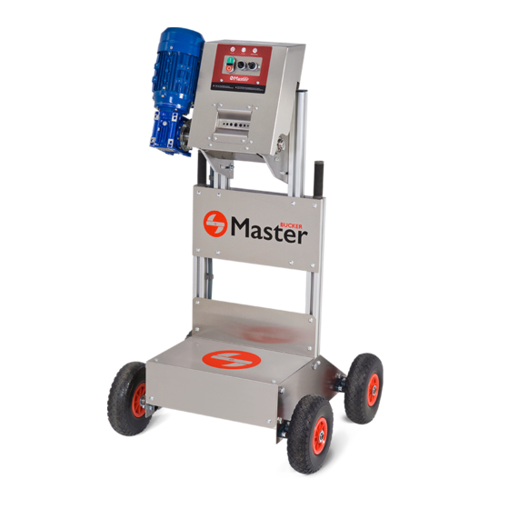
MB Bucker 500 La MB Bucker 500 es la descogolladora idónea para grandes producciones en espacios reducidos. Gracias a sus Indicaciones generales Objetivo del manual Este manual de instrucciones hace que el usuario de la máquina se familiarice con: La forma de trabajo El uso de la máquina... - Page 4 Los dispositivos de seguridad como interruptores y protecciones, no pueden ser desmantelados bajo ninguna circuns- tancia. Asegurar que la MB Bucker 500 está correctamente cerrada y los botones apagados, antes de realizar cualquier manteni- miento en ella. No acercar al cabezal de entrada del equipo las manos o cualquier otro objeto que pueda dañar a éste o al operario.
-
Page 5: Transporte
Controles a realizar antes de conectar Modo hibernación Con el objetivo de mantener la MB Bucker 500 de forma óptima para su primer uso, se suministra en modo hibernación. Esto al contacto entre ellos. Será necesario ajustar los rodillos antes del primer uso, manteniendo la MB Bucker 500 desconectada de la corriente en todo momento. - Page 6 Ajuste de rodillos Si observa una falta de succión de las ramas introducidas en el cabezal de la máquina, es debido a un incorrecto ajuste y una llave allen nº4 (E). IMPORTANTE: desconectar la máquina de su fuente de alimentación. Pulsar el botón OFF, de color rojo, presente en el Desatornillar los cuatro tornillos del carenado cuadro de mando y desconectar el equipo de la...
-
Page 7: Separar Rodillos
Repetir el proceso en el otro lado. Una vez ajustados los rodillos, colocar el carenado frontal en la MB Bucker 500. inferior tal como se muestra en la siguiente imagen para bloquearla. Repetir el proceso en el otro lateral. - Page 8 Aun así, tenemos que prestar atención al modo de uso de la máquina y las condiciones del producto. La MB Bucker 500 puede utilizarse con todo tipo de plantas herbáceas y/o semi-leñosas. Todas aquellas plantas que no sean de esta naturalidad no pueden ser procesadas.
- Page 9 Desconectar el equipo de la fuente de alimenta- Utilizar la llave allen nº6 (F) y desatornillar, los dos ción. tornillos traseros marcados en la imagen, lo los dos tornillos en ambos lados con ayuda de la llave allen Nº 6 (F). Funcionalidad cabezales CABEZAL REDONDO CABEZAL ESTRELLA...
-
Page 10: Cambio De Cabezal
Seguridad MB Bucker 500 La MB Bucker 500 está equipada con un dispositivo de seguridad que garantiza la protección del operario durante el pasador se encuentra insertado en la base. En el momento en que se retira el carenado, estos dos elementos dejan... - Page 11 PASADOR BASE Hasta que el carenado frontal no vuelva a colocarse correctamente y el pasador se inserte en la base, la máquina no se encenderá y no estará operativa. De esta manera se evita exponer al operario a cualquier riesgo de atrapamiento por tracción de los rodillos.
- Page 12 Pulsar el botón OFF, de color rojo, presente en el Con ayuda de la llave allen Nº 4 (E), en primer cuadro de mando y desconectar el equipo de la lugar, desatornillar los cuatro tornillos del cabezal fuente de alimentación. y a continuación extraer el cabezal y limpiarlo como se muestra en las siguientes dos imágenes.
- Page 13 Una vez separados los rodillos, pulverizar con tuerca inferior para bloquearla tal como se mues- recauchutada, haciendo inciso en los cabezales y tra en la siguiente imagen. Repetir el proceso en el los rodillos. lado opuesto. Aprovechar para comprobar que todos los componentes están en buenas condiciones. Una vez todos los componentes estén limpios y secos, apretar los rodillos para volver a montar el inferior que se muestra en la siguiente imagen.
-
Page 14: Eliminación De Residuos
Volver a situar el cabezal en el carenado frontal, tal Fijar el carenado frontal atornillando los cuatro y como se muestra en la imagen. Atornillar los tornillos delanteros y los cuatro tronillos traseros. cuatro tornillos del cabezal con ayuda de la llave allen nº4 (E). -
Page 15: Datos Generales
Datos generales Modelo MB BUCKER 500 Potencia 750 W Año de fabricación 2021 País España Nombre de la empresa MASTER PRODUCTS INOXIDABLE, S.L. Dirección Veïnat de la Banyeta nova, 10 Localidad Palol de Revardit Teléfono (+34) 972 299 355 Email info@masterproducts.es... - Page 17 General Instructions Safety symbols Safety for the operator Aim of the Manual Where to keep the manual Who can use the MB Bucker 500 How to stop the MB Bucker 500 Warranty Contents of the box Repairing the MB Bucker 500...
-
Page 18: Mb Bucker 500
MB Bucker 500 General Instructions Aim of the Manual This instruction manual familiarizes the user with: How to work with the machine The use of the machine Safety instructions Maintenance Where to keep the manual Keep the instruction manual close to the machine. Instructions should always be at hand. It should be kept in a safe and dry place. - Page 19 Failure to observe these instructions may lead to misuse of the article in question. Safety for the operator Who can use the MB Bucker 500 How to stop the MB Bucker 500 Repairing the MB Bucker 500...
-
Page 20: Transport
Transport Pallet 75 x 80x 140 cm = 130 kg // Net weight MB Bucker 500 = 70 kg Electrical connection The MB Bucker 500 machine should be connected to a single-phase 230 V/50-60 Hz electrical power supply. Placement suitable for indoor use and under no circumstances should the electrical part be exposed to water. - Page 21 Adjusting the rollers Press the red OFF button on the control panel and Unscrew the four bolts of the front fairing and the must be stopped and disconnected before manipula- tion. Tightening the rollers Unscrew the lower nut shown in the image (1) as shown in the following images.
-
Page 22: Separating The Rollers
Repeat the process on the other side. rollers separate. Repeat the process on the other side. front fairing on the Master Bucker 500. nut as shown in the following image to lock it. Repeat the process on the other sidel. - Page 23 It may be helpful to tilt the upper part to ensure the comfort of each operator so that the operator can better adapt to the working conditions. The MB Bucker 500 can be tilted as shown below. Only a No. 6 Allen key (F) is...
- Page 24 Use the No. 6 Allen key (F) to unscrew the two rear both sides again using the No. 6 Allen key (F). Head functionality ROUND HEAD STAR HEAD TUBULAR HEAD This is suitable for proces- This is suitable for proces- This is designed for proces- sing most stems.
-
Page 25: Changing The Head
Using the No. 4 Allen key (E) unscrew the four head Select the new head and place it in the correct position. Tighten the four bolts of the new head image. Connect the MB Bucker 500 to a power supply to operate it again. MB Bucker 500 Safety... - Page 26 BASE BASE IMPORTANT: Maintenance Cleaning steps shown below.
- Page 27 Press the red OFF button on the control panel and as shown in the following two images. Using the No. 4 Allen key (E) unscrew the four bolts of the front fairing and the four bolts of the rear protection. Screw the upper nut shown in the following image lower nut as shown in the image.
- Page 28 lower nut to lock it as shown in the following attention to the heads and rollers. image. Repeat the process on the opposite side. Take the opportunity to check that all components are in good condition. Unscrew the lower nut shown in the following rollers get closer together.
-
Page 29: Waste Disposal
Tighten the four head bolts using the bolts and the four rear bolts. No. 4 Allen key (E). Medidas Connect the MB Bucker 500 to a power supply to operate it again. Waste disposal Waste must be disposed of according to the corresponding national regulations. -
Page 30: General Details
(+34) 972 299 355 Email info@masterproducts.es Website www.masterproducts.es CE DECLARATION OF CONFORMITY The company: Telef./Fax: (+34) 972 299 355 E-mail: info@masterproducts.es VAT No ESB55310817 Declares under its sole responsibility that the machine: MB Bucker 500 with serial number: Harmonised standards: Signatories: CMP-1461-00-A...