
Related Manuals for Emerson Magtech LTM−350 Series


Summary of Contents for Emerson Magtech LTM−350 Series
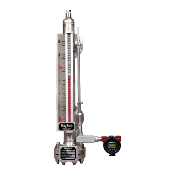
- Page 1 August 2020 Reference Manual L231040 Rev AD Magtech LTM−350 Series Magnetostrictive Level Transmitter for Liquid Level Measurement Instruction and Operations Manual...
- Page 2 August 2020 Reference Manual L231040 Rev AD NOTICE Read this manual before working with the product. For personal and system safety, and for optimum product performance, make sure that you thoroughly understand the contents before installing, using or maintaining this product. For Equipment service or support needs: Customer Central: +1-800-221-3653 (8:00 a.m.
-
Page 3: Table Of Contents
August 2020 Reference Manual L231040 Rev AD Table of Contents Section 1: Transmitter Overview Page General Description Level Transmitter MLI Mounted Transmitter Direct Insertion Transmitter Section 2: Instrument Description Page Transmitter Detailed Operation Theory of Operation Section 3: Installation and Wiring Page MLI Mount Transmitter Installation Direct Insertion Transmitter Installation... - Page 4 August 2020 Reference Manual L231040 Rev AD Section 7: LTM-350 has HART Protocol Page Hart Protocol: General Information Hart Protocol Menus and Flowchart Section 8: LTM-350 in a SIS Page General Safety Guidelines LTM-350 Safety Ratings LTM-350 Proof Test Safety Inspection Identification Section 9: Warranty Page...
-
Page 5: Section 1: Transmitter Overview Page
August 2020 Reference Manual L231040 Rev AD Section 1: Transmitter Overview 1.0 General Description 1.2 MLI Mounted Transmitter The LTM-350 is an electronic field instrument, suitable for installation in hazardous and non-hazardous industrial The LTM-350 may be strapped to the side of the Magtech areas. -
Page 6: Section 2: Instrument Description Page
August 2020 Reference Manual L231040 Rev AD 2.1 Theory of Operation Note: When a stilling well is The LTM-350 Level Transmitter is based on the principle of used, care should be magnetostriction first used for digital delay lines and later exercised when installing for precision distance or displacement in the machine tool the tube to center it in... -
Page 7: Section 3: Installation And Wiring Page
August 2020 Reference Manual L231040 Rev AD Calibration routines are included in the software to the 0% and 100% points for any distance desired. Even reverse 2. Primary Level and Interface Level: A second float calibration is a simple task using the software routines. may be added below the first, and the second Reverse calibration is desirable if ullage instead of level is output will be calibrated automatically. -
Page 8: Direct Insertion Transmitter Installation
August 2020 Reference Manual L231040 Rev AD accurate measurement because the active region of the probe is too short. When placing an order for a transmitter 3.2 General Installation Guidelines to accompany an existing MLI it is important to indicate the The basic steps to installing the LTMs are: style of the MLI, the temperature and the center-to-center dimensions. -
Page 9: Recommended Wiring
August 2020 Reference Manual L231040 Rev AD most nearby posts or pipes with hose clamps. The drawing below depicts a gage mounted transmitter in the top mount Transmitter B is a top mount with elbow, usually utilized remote electronics configuration. when there are temperature or head room issues. -
Page 10: Section 4: Specifications Page
August 2020 Reference Manual L231040 Rev AD Housing: Explosion Proof, Dual The following below is the Hart Topology. Compartment, 1/2” npt, Epoxy Coated Aluminum (Standard) Explosion Proof, Dual Compartment, 1/2” npt, Stainless Steel (Model LTM-351 only) Hazardous Location Approvals: FM – Exp Cl I, Div. I Grp. BCD, Cl II, Grp. -
Page 11: Transmitter Sensor Tube
August 2020 Reference Manual L231040 Rev AD The pushbuttons are timed not pressurized. It does Make sure that the electronics are not in write – not matter how hard/firm you press them. The buttons protect mode. The menu order can change and new menus depend on the length of time they are pressed. - Page 12 August 2020 Reference Manual L231040 Rev AD original point. It is recommended to leave this at 0.00 most of the time unless a special Configuration Screens (Up/ Down arrows choose circumstance arises. Press enter to go the options) next screen. Press Select to Enter Select Upper Range Value (URV): Sel URV...
-
Page 13: Features Description
August 2020 Reference Manual L231040 Rev AD Trim Digital-Analog-Converter (DAC): TrimDAC? These are factory set parameters used to provide an accurate 4.000mA and 0.000mA. Rate of Change (RoC) Filter: This parameter should not be changed as Magtech uses NIST traceable equipment to The RoC filter is a continuous monitor of how fast (the rate) calibrate our transmitters and only accredited the level is rising and falling. - Page 14 August 2020 Reference Manual L231040 Rev AD Select Defaults Load Factory Sensor1 Sensor2 Sensor3 Loaded * Avg PW and 4mA Sat menus/options are available in software revisions 1.02.00 or higher. Select Defaults ComPort: Save Sensor1 Sensor2 Sensor3 Saved This menu is currently only utilized at the factory and will not assist in any troubleshooting.
- Page 15 August 2020 Reference Manual L231040 Rev AD Deadzone: hold time can increase the deadband near the electronics. Please contact the factory for guidance with this parameter. This menu is mainly utilized at the factory to achieve optimal linearity near the deadband close to the electronics. 8.
- Page 16 August 2020 Reference Manual L231040 Rev AD the protruding screws (spanner screws) to pull out Change Signal (ChngSgnl): the electronics module. Alternate pulling on the The next and final menu in the special features menu is screws in order to prevent damage to the “ChngSgnl”...
-
Page 17: Section 6: Transmitter Calibration And Troubleshooting Page
August 2020 Reference Manual L231040 Rev AD 4mA Saturation (4mA Sat): The LTM-350 transmitters are protected from incorrect calibration so if something is done incorrectly it will display When turned on this feature is designed to cause the “Span Error” on the LCD for 5 seconds and then return to transmitter output to go to 3.80mA saturation if the level the beginning of the “Trim Sensor”... -
Page 18: Basic Troubleshooting
August 2020 Reference Manual L231040 Rev AD 2. Water damage 6.2 Basic Troubleshooting Water damage to the electronics module or sensor probe. Potential Possible This is potentially the most severe case the symptoms are Symptom Issue/Problem Solution unpredictable. If there is any suspicion that the transmitter The transmitter is may have incurred water damage please contact the factory polarity protected. -
Page 19: Changing Signal Parameters
August 2020 Reference Manual L231040 Rev AD Cycle power rapidly Possible Resolution: LCD did not initialize (this may have to Increase Energy Settings: properly be done a few times). 1. Unlock the pushbuttons by moving the blue jumper Local display Replace electronics to the left, Hold the UP button for 1sec showing dark... - Page 20 August 2020 Reference Manual L231040 Rev AD 7.1 Hart Protocol: Menus and Flowchart The following is a flow chart of our HART menu structure. This flow chart can be utilized to access desired parameters and operations when using a handheld communicator or a HART enabled host system. Hart Protocol: Menus and Flowchart Device Setup Process Variables...
- Page 21 August 2020 Reference Manual L231040 Rev AD Load Save User 3 Slot Load Save Signal Setup Energy DC Offset Hold Time Digital Level Alarms Alarms are: (Enabled/Disabled) Alarm High High Alarm High Alarm Low Alarm Low Low Level Alarm Status Output Condition Analog Output Loop Current Mode...
- Page 22 August 2020 Reference Manual L231040 Rev AD 8.2 LTM-350 Proof Test Section 8: LTM-350 in a SIS 1. To avoid any false alarms take appropriate steps to notify control room that the instrument is being 8.0 General Safety Guidelines tested. 2.
- Page 23 FACTORY AND ARE FULLY PROTECTED AGAINST DAMAGE OR LOSS DURING SHIPMENT. ANY CLAIMS FOR PARTS DAMAGED DURING SHIPMENT SHOULD BE SUBMITTED WITHIN 15 DAYS OF RECEIPT OF GOODS BY CUSTOMER. Emerson Automation Solutions- Magtech 3902 Magnolia Road, Pearland, Texas, 77584-1610, USA...
- Page 24 August 2020 Reference Manual L231040 Rev AD Section 10: China RoHS 10.0 LTM-350 Model Disclosure 管控物质超过最大浓度限值的部件型号列表 含有 LTM-350/351 China RoHS List of LTM-350/351 Parts with China RoHS Concentration above MCVs 有害物质 / Hazardous Substances 六价铬 多溴联苯 多溴联苯醚 部件名称 铅 汞 镉...