Table of Contents
Advertisement
Available languages
Available languages
Quick Links
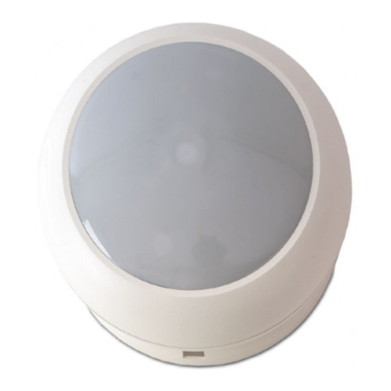
EV660 Series Ceiling Mount Detector Installation
Sheet
EN DA DE ES FR
IT
1
!
3
EV669
Form A
ALARM
SPARE
EV666-D
1
2
3
4
5
Form C
NC
C
NO
ALARM
5
EV669
33 Ω
© 2019 UTC Fire & Security Americas Corporation, Inc.
NL NO SV
Factory default
O N
TAMPER
LATCH WALK
SPARE
TEST
6
7
8
9
10
EV666-D
33 Ω
2
(1)
(4)
(6)
(8)
4
9
8
1 / 17
(2)
SWITCH
On
Off
Description
.
LED enable
LED on
LED off
O
N
Processing
Bi-curtain
Standard-4D
Det. pattern
180
o
360
o
(3)
1
2
3
(5)
5 cm
1
2
3
4
5
6
7
8
9
10
NC
C
NO
+
ALARM
TAMPER
SPARE
(7)
(3)
(6)
(9)
(7)
1 2 3 4 5 6 7 8 9
2
7
3
6
4
5
P/N 143197999-4 • REV H • ISS 05MAR19
1
Advertisement
Table of Contents

Related Manuals for Interlogix EV660 Series


Summary of Contents for Interlogix EV660 Series
- Page 1 EV660 Series Ceiling Mount Detector Installation Sheet EN DA DE ES FR NL NO SV SWITCH Description LED enable LED on LED off Processing Bi-curtain Standard-4D Det. pattern 5 cm ALARM TAMPER SPARE EV669 Factory default Form A ALARM TAMPER...
- Page 2 4 is set to ON. Description Mounting instructions The EV660 series includes models EV666-D with Form C relay, and EV669 with Form A relay. These are ceiling mount See Figure 2. PIR detectors with 360° coverage.
- Page 3 To mount the sensor module to the mounting plate use the Access to the mirror inside the sensor screw (items 6 and 7), which is placed for transport in the module mounting plate. This access is only required when masking individual curtains. The curtain directions 1 to 9 clockwise (item 2) are indicated in the mounting plate (curtain no.
- Page 4 Switch 1: Programvalg af kontrolspænding (CV) Contact information ON: lnverteret. Lav spænding (0 V) vil tillade GANGTEST og LATCH-funktion. www.utcfireandsecurity.com or www.interlogix.com OFF: Standard. Høj spænding (12 V) vil tillade GANGTEST og For customer support, see www.utcfssecurityproducts.eu. LATCH-funktion (fabriksindstilling). Switch 2: Programvalg for LED DA: Installationsvejledning ON: LED ved alam/gangtest altid i drift (fabriksindstilling).
- Page 5 0.3 til 3.0 m/s Kontakt information Alarmudgang 100 mA vid 28 V 100 mA vid 28 V Type C Type A (NC), www.utcfireandsecurity.com eller www.interlogix.com. (se Fig. 5) (se Fig. 5) Kundesupport: www.utcfssecurityproducts.eu Alarmtid min 2.5 Sec. Sabotage udgang 100 mA vid 28 V Temperaturområde...
- Page 6 • Durch die Doppelvorhangzonen Funktion können Verdecken des Erfassungsbereichs des Melders durch Hinweis: große Objekte, z. B Möbel Falschmeldungen vermieden werden. In dieser Betriebsart muß eine eindringende Person von zwei Vorhängen detektiert Bei einer Montagehôhe oberhalb des empfohlenen Höhen- werden um einen Alarm zu verursachen. bereichs (2,5 bis 5,0 m) wird die Erfassungsempfindlichkeit „OFF“: Standard-4D-Signalverarbeitung.
-
Page 7: Hinweise Für Vds-Installationen
93% Website: www.utcfssecurityproducts.eu/recycle/ Ø 138 x 75 mm Abmessungen Gewicht 190 g Kontaktinformation Anzahl Zonen www.utcfireandsecurity.com oder www.interlogix.com. Max.Erfassungsbereich 10 m Radius; 20 m Diameter Kundendienst: www.utcfssecurityproducts.eu Gehäuse nach (mit versiegelter IP30 IK04 Kabeleinführung) ES: Instrucciones de instalación Hinweise für VdS-Installationen In VdS-Installationen muß... -
Page 8: Especificaciones Técnicas
Levante la placa de montaje (elemento 1) tal como se ha ocurrido alguna alarma durante el periodo activado, se indica. enciende intermitentemente el LED en el detector (o los detectores) que se han activado. Al poner de nuevo “CV” Sujete la placa de montaje al techo en la posición (activar el sistema), se ponen a cero la memoria y las señales deseada, utilizando los agujeros de montaje (elemento 3). -
Page 9: Información De Contacto
Información de contacto La direction des rideuax 1–9 dans le sens des alguilles d'une montre (objet 2) est indiquée sur la plaque de montage www.utcfireandsecurity.com o www.interlogix.com (le rideau no. 5 est la rideau central). Servicio técnico: www.utcfssecurityproducts.eu P/N 143197999-4 • REV H • ISS 05MAR19... -
Page 10: Mémoire D'alarme
Réglage commutateur DIP • Pour activer la LED sans connexion à une tension « CV » extérieure au détecteur, mettre un pont entre les bornes 2 et 10. Interrupteur 1: Programmation de la tension de contrôle (CV) Accès aux miroirs à l’intérieur du module «... - Page 11 (La tenda 5 è quella centrale). Contact Impostazione commutatore DIP-switch www.utcfireandsecurity.com ou www.interlogix.com Assistance clientèle : www.utcfssecurityproducts.eu Interruttore 1: Programmazione tensione di controllo (CV) “ON”: Logica inversa, per abilitare le funzioni WALK TEST (TEST COPERTURA) e LATCH è richiesto un riferimento IT: Istruzioni d’installazione...
-
Page 12: Certificazione E Conformità
2014/35/UE. Per ulteriori informazioni, vedere Esempio: In figura 4 è mostrato come mascherare i campi di www.utcfireandsecurity.com o copertura 4 e 8. www.interlogix.com. 2012/19/EU (Direttiva WEEE): I prodotti Caratteristiche tecniche contrassegnati con questo simbolo, non possono essere smaltiti nei comuni contenitori per lo... -
Page 13: Nl: Installatie Instructies
Contatto per informazioni Instelling DIP-switch www.utcfireandsecurity.com o www.interlogix.com. Schakelaar 1: Programmering van de stuurspanning (CV) Assistenza clienti: www.utcfssecurityproducts.eu “ON”: Logica geïnverteerd, 0 Volt voedingsspanning is vereist om de LOOPTEST- en LATCH-functies vrij te geven. “OFF”: Standaard logica, 12 Volt voedingsspanning is vereist... - Page 14 Max. rimpelspanning max. 2 V (bij 12 V ) Contact informatie Stroomverbruik Normale werking 9 mA 9 mA www.utcfireandsecurity.com of www.interlogix.com. Alarm 15 mA max. 15 mA max. Klantenondersteuning: www.utcfssecurityproducts.eu Bewegingssnelheid 0.3–3.0 m/s Alarmuitgang 100 mA bij 28 V...
- Page 15 Monteringshøyde: min. 2.5 m — max. 5.0 m. etter en gåtest vil indikeringen av alarmen komme frem. Minnet nullstilles når CV tilkobles (systemet resettes) til Dekningsområde kan justeres ±15° (maks 30°) ved å vri klemme 9. monteringsplaten før man strammer skruene. •...
- Page 16 DIP-switch inställning Notera: För att uppfylla kraven i EN 50131-2-2 och SSF 1014 Kontaktinformasjon v5 måste Switch 2 ställas i frånläge (de andra dipswitcharna i www.utcfireandsecurity.com eller www.interlogix.com. fabriksinställning). Kundestøtte: www.utcfssecurityproducts.eu Switch 1: Val av signallogik (styrspänning) (CV) ON: Inverterad (negativ) logik, en låg spänning (0 V) krävs för SV: Installationsinstruktioner att aktivera GÅNGTEST och LATCH-ingång (larmminne).
-
Page 17: Information Om Regler Och Föreskrifter
Type C, växlande Type A (brytande), Kontaktinformation reläkontakt (fig. 5) potentialfritt relä (fig. 5) Larmtid min 2.5 s www.utcfireandsecurity.com eller www.interlogix.com Sabotageutgång 100 mA till 28 V Kundsupport: www.utcfssecurityproducts.eu Temperaturområde −10 till +55°C P/N 143197999-4 • REV H • ISS 05MAR19...