Cleveland 24CGA10.2 Installation And Maintenance Instructions Manual
Dual gas steam generator & convection steamer
Hide thumbs
Also See for 24CGA10.2:
- Operator's manual (30 pages) ,
- Parts manual (23 pages) ,
- Specifications (2 pages)
Table of Contents
Advertisement
Advertisement
Table of Contents

Related Manuals for Cleveland 24CGA10.2


Summary of Contents for Cleveland 24CGA10.2
- Page 1 Installation and Maintenance Instructions Dual Gas Steam Generator & Convection Steamer 24CGA10.2 24CGA6.2 Series: Gemini Model Nos. 24CGA6.2, 24CGA10.2 1333 East 179 Street Cleveland, Ohio 44110 Phone: (216) 481-4900 Fax: (216) 481 3782 Part No. GEMINI-INM B 7/02...
-
Page 2: For The Installer
BY ALL USERS OF THIS EQUIPMENT. THIS INFORMATION SHOULD BE OBTAINED FROM YOUR LOCAL GAS SUPPLIER. ALL SERVICE MUST BE PERFORMED BY A QUALIFIED CLEVELAND RANGE AUTHORIZED TECHNICIAN. The wiring diagram is located on the back of the lower front panel. -
Page 3: Table Of Contents
CHAPTER 1 PRODUCT IDENTIFICATION ________________________________________ A. MODEL NUMBER ________________________________________________________ B. SERIAL NUMBER ________________________________________________________ C. PRODUCT INFORMATION PLATE D. 24CGA6.2 PRODUCT VIEW E. 24CGA10.2 PRODUCT VIEW _______________________________________________ CHAPTER 2 INSTALLATION INSTRUCTIONS _____________________________________ A. GENERAL ______________________________________________________________ B. INSTALLATION OF THE STEAMER 1. Locating the Steamer a. -
Page 4: Chapter 1 Product Identification
CHAPTER 1 PRODUCT IDENTIFICATION Cleveland Range, Inc. assigns two product identification numbers to each steamer: a model number and a serial number. The model number identifies the product characteristics. The serial number identifies the individual unit. A. MODEL NUMBER This manual covers the Gemini Model No. 24CGA6.2 and 24CGA10.2 Dual Steam Generator and Convection Steamer. -
Page 5: 24Cga6.2 Product View
D. 24CGA6.2 PRODUCT VIEW PRODUCT INFO. PLATE ON LEFT ACCESS PANEL POWER ON/OFF CONTROLS DRIP TRAY WIRING DIAGRAMS ARE LOCATED ON THE BACK OF FRONT ACCESS PANEL FRONT ACCESS PANEL Figure 1-2. Gemini 6-Pan Dual Atmospheric Steam Generator FLUE OUTLET DESCALING PORTS MAIN... -
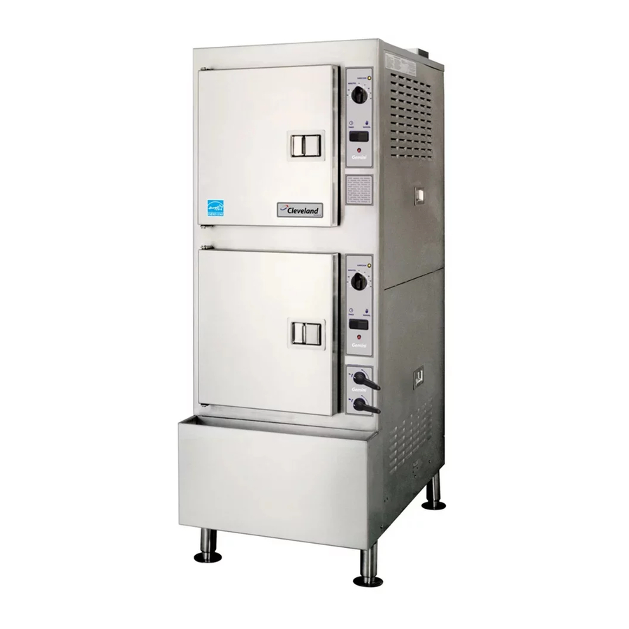
Page 6: 24Cga10.2 Product View
E. 24CGA10.2 PRODUCT VIEW POWER ON/OFF CONTROLS (UPPER) PRODUCT INFO PLATE ON LEFT ACCESS PANEL DRIP TRAY WIRING DIAGRAMS ARE LOCATED ON THE BACK OF FRONT ACCESS PANEL FRONT ACCESS PANEL Figure 1-3. Gemini 10-Pan Dual Atmospheric Steam Generator FLUE OUTLET... -
Page 7: Chapter 2 Installation Instructions
CHAPTER 2 INSTALLATION INSTRUCTIONS A. GENERAL This equipment should only be installed by qualified, professional plumbers, pipe fitters, and electricians. · The installation of this steamer must conform with the Basic Plumbing Code of the Building Officials and Code Administrators International, Inc. (BOCA), the National Fuel Gas Code, ANSI Z223.1-(latest edition) or the Natural Gas Installation Code CAN/CGA-B149.1 or the Propane Installation Code CAN/CGA-B149.2 as applicable, The National Electrical Code, ANSI/NFPA No. -
Page 8: Locating The Steamer
Malfunctions and equipment damage may result from improper mounting. Malfunctions and/or damage resulting from improper mounting are not covered by the equipment warranty. The steamer MUST BE LEVEL BOTH FRONT TO BACK AND SIDE TO SIDE in all mounting arrangements. Catastrophic damage will result from shifting the steamer more than out of level with power supplied to the unit. - Page 9 1-1/4" IPS line size, 3/4" connection NATURAL PROPANE Piping 3/4" N.P.T Piping 3/4" N.P.T. 50,000 Supply pressure Supply pressure Generator 4.50" W.C. Min. 11.00" W.C. Min. 14.00” W.C. Max. 14.00” W.C. Max. 100,000 total Manufacturer must be notified if unit will be used above 2,000 feet Figure 2-1 Gemini 24CGA6.2 Dimensions and Clearances OPERATING...
- Page 10 4.50" W.C. Min. 11.00" W.C. Min. 14.00” W.C. Max. 14.00” W.C. Max. 144,000 total Manufacturer must be notified if unit will be used above 2,000 feet Figure 2-2 Gemini 24CGA10.2 Dimensions and Clearances OPERATING CLEARANCE SECONDARY CLEARANCE ELECTRIC COLD WATER 120V-1Phase, 60 Hz.
-
Page 11: Exhaust Hood Requirements
b. Exhaust Hood Requirements The Gemini gas steamer MUST be installed under an exhaust hood. The exhaust hood must extend over the gas flue opening on top of the steamer and meet the following requirements: 1). The Gemini gas steamer must be vented in accordance with all local, state and national codes for venting gas fired appliances. -
Page 12: Install The Free Air Vented Drain Lines
3. Install the Free Air Vented Drain Lines Furnishing and installing the drain line is the responsibility of the owner and/or installer. Figure 2-4 illustrates a drain layout recommended by Cleveland Range. DEATH, INJURY, AND EQUIPMENT DAMAGE could result from improper installation of the drain outlet lines. -
Page 13: Install Gas Supply Lines
4. Install Gas Supply Lines a. Gas Supply Requirements 1) Make sure the gas supply type matches the type of gas shown on the rating plate. 2) Make sure that the gas supply pressure does not exceed 14” water column, and falls within the acceptable gas pressure range shown below: ·... -
Page 14: Testing Gas Supply Lines
c. Testing Gas Supply Lines LEAKING GAS CAN CAUSE FIRE OR EXPLOSION WITH PROPERTY DAMAGE, INJURY OR LOSS OF LIFE. If the installer smells gas, or suspects there is a gas leak, immediately refer to the posted gas leak instructions. The posted instructions are provided by the local gas supplier, and supersede any other instructions. -
Page 15: Water Supply Requirements And Installation
6. Water Supply Requirements and Installation a. Water Supply Requirements Using water not within the limits specified in this manual could void or reduce Cleveland Range’s warranty coverage of the steamer. 1). Water Quality As with any steam generating equipment, poor water quality degrades the performance of the steamer. -
Page 16: Setting The Descale Required Light
Table 2-1. Minimum Water Quality Requirements Scale Forming Factors Total Dissolved Solids Silica Alkalinity Corrosion-Causing Factors: Free Chlorine Chloride PH factor 2). Water Supply System Provide a water supply system that fulfills the requirements of the limits listed in Table 2-1. The supply must provide a minimum dynamic pressure of 35 psi (2.4 kg/cm pressure of 60 psi (4.1 kg/cm ·... - Page 17 2). Determining the Timer Setting The recommended setting of the Descale Required light is determined by the quality of the water supply. Table 2-2 suggests appropriate timer settings. 3). Switches Determine Timer Setting The Timer Module contains a bank of miniature switches that determine the timer setting.
-
Page 18: Install Water Supply Lines
The steamer has two 3/8-inch IPS fittings (Model 24CGA6.2) or two 1/4-inch IPS fittings (Model 24CGA10.2) for the water connections to the generator and to the condenser. These fittings are detailed as D and E in Figure 2-1 or 2-2. -
Page 19: Testing Water Supply Lines
Gemini Condenser Solenoids Steam Generator Solenoids Figure 2-11 Cleveland Range Single Water Supply Arrangement when Using Separate Conditioned Feed Water Supply May be installed internal to the steamer on some models) A 40 or 50-mesh water strainer (dirt filter) of one of the types and construction... -
Page 20: Installation Checkout
1. Installation Checkout Use the Installation Checklist Table 2-3, to check the overall installation. TASK Preparation Verify Electric Power Requirements. Verify Gas Supply Requirements Verify Exhaust Hood Requirements Test supply water quality. Check operating location clearances Installation Verify steamer is level. Check drain line connection. -
Page 21: Burner Ignition Test (Lighting And Shutdown Instructions)
Do not alter any adjustments on this electronic control or automatic gas valve. If adjustment is required, contact an authorized service center. Cleveland Range is in no way responsible for the operation or safety of this equipment if the controller, valve or igniter probe is adjusted by anyone other than a Cleveland Range authorized service representative. -
Page 22: Shutdown Instructions
This should be done at a union or connection as close as possible to the inlet of the automatic gas valve. 7). If the burner does not light after the third attempt, call a Cleveland Range authorized service representative to adjust the burner controls. -
Page 23: Startup Procedure
a. Startup Procedure 1. Check that the water supply line valves are open. 2. Check that the main manual gas valve is open. 3. Open the steamer door. Check for proper installation of the drain screen, slide racks, and door gasket assembly. -
Page 24: Operating Tests And Final Checkout Procedure
c. Operating Tests and Final Checkout Procedure (Continue from Blowdown Inspection) (Sequence of Operation) When checking inside the steamer always open the door slowly and stand to the side and back away from the steamer. Water leaking from the door gasket can be a sign of a blocked drain. If the drain is blocked, hot water can accumulate inside the compartment and spill out when the door is opened. - Page 25 · After a few minutes steam begins to enter the compartment from the nozzles. A small quantity of water may drip from the nozzles until steam clears the lines. · After a few more minutes the compartment will reach cooking. The thermostat will close temperature (the pause light will go OFF for mechanical timer units) and the condenser solenoid clicks open and condenser flow starts.
-
Page 26: Chapter 3 Preventative Maintenance And Troubleshooting
c) If the probe cylinder water level drops below the upper probe, 15 to 20 seconds later the water fill valve opens and fills the generator. When the probe cylinder water level is above the middle probe, the burners turn ON. A dull roaring sound indicates the burners are firing and the unit is generating steam. -
Page 27: Yearly Maintenance
(2) Yearly Maintenance Clean Water Line Strainer Clean the water line strainer at least once a year as follows: NOTE: When the steamer is first installed, check the strainer more frequently to find out how often it must be cleaned. 1. - Page 28 Repair or replace water supply line. See note # 1. Turn OFF electricity at main external power switch. See note # 1. Descale steam generator with Cleveland Range approved descaler. The unit requires a minimum inlet pressure of 4.5 inches W.C. to operate.
- Page 29 Turn ON/OFF lever/switch to the full OFF position to start the proper blowdown operation. See note #1. Press switch to reset desccale timer Descale unit with Cleveland Range approved descaler. After descaling is completed, press switch to reset descale timer. See note #1.
- Page 30 TROUBLESHOOTING NOTES 1. If problem is inside the steamer, call an authorized service representative. Cleveland Range, Inc. will not pay for warranty repairs by unauthorized repair centers. 2. Proper installation of the steamer is the responsibility of the owner or installer. A qualified installer or technician should be contacted to correct the installation.