Lennox 13HPX Series Unit Information
Hide thumbs
Also See for 13HPX Series:
- Installation instructions manual (32 pages) ,
- Brochure & specs (2 pages) ,
- Installation instructions manual (17 pages)
Advertisement
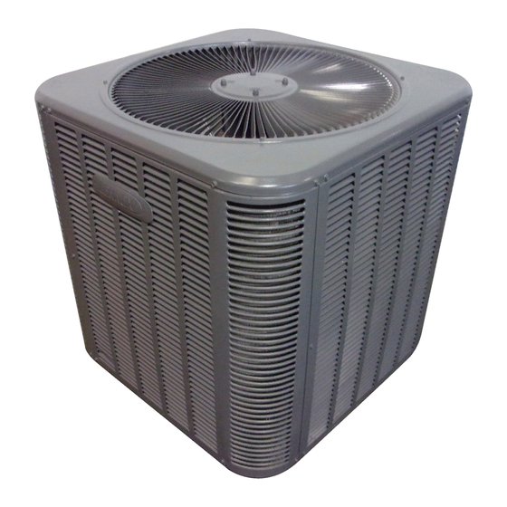
Service Literature
The 13HPX is a residential split-system heat pump. The
series is designed for use with expansion valves (TXV) and
R−410A refrigerant. All 13HPX units utilize scroll compressors.
13HPX series units are available in 1 1/2, 2, 2 -1/2, 3, 3
-1/2, 4 and 5 ton capacities. All major components (indoor
blower and coil) must be matched according to Lennox rec-
ommendations for the compressor to be covered under
warranty. Refer to the Engineering Handbook for approved
system matchups.
This manual is divided into sections which discuss the
major components, refrigerant system, charging proce-
dure, maintenance and operation sequence.
Information contained in this manual is intended for use by
qualified service technicians only. All specifications are subject
to change.
ELECTROSTATIC DISCHARGE (ESD)
Precautions and Procedures
CAUTION
Electrostatic discharge can affect electronic
components. Take precautions during unit instal-
lation and service to protect the unit's electronic
controls. Precautions will help to avoid control
exposure to electrostatic discharge by putting
the unit, the control and the technician at the
same electrostatic potential. Neutralize electro-
static charge by touching hand and all tools on an
unpainted unit surface before performing any
service procedure.
WARNING
Refrigerant can be harmful if it is inhaled. Refrigerant
must be used and recovered responsibly.
Failure to follow this warning may result in person-
al injury or death.
MODEL NUMBER IDENTIFICATION
Nominal SEER
Unit Type
HP = Heat Pump Outdoor Unit
Refrigerant
X = R−410A
Corp. 0619−L4
Revised 04−2009
13HPX SERIES UNITS
In order to avoid injury, take proper precaution when
lifting heavy objects.
V Brazing Procedure
VI Diagrams
13 HP X − 024 − 230 − 2
Page 1
CAUTION
Table of Contents
. . . . . . . . . . . . . . . . . . .
. . . . . . . . . . . . . . . . . . . . . . . . . . . . .
. . . . . . . . . . . . . . . . . . . . . . . . . . .
. . . . . . . . . . . . . . . . . . . . . . . . . . . . . . . . . . .
. . . . . . . . . . . . . . . . . . . . . . . . . . . . . . . .
. . . . . . . . . . . . . . . . . . . . . . . . . . .
. . . . . . . . . . . . . . . . . . . . . . . . . . . . . . . . . .
Minor Revision Number
Voltage
230 = 208/230V−1phase−60hz
Nominal Cooling Capacity
018 = 1.5 tons
024 = 2 tons
030 = 2.5 tons
036 = 3 tons
042 = 3.5 tons
048 = 4 tons
060 = 5 tons
061 = 5+ tons
© 2006 Lennox Industries Inc.
13HPX
1.5 to 5 ton
2
4
9
11
14
14
15
Advertisement

Related Manuals for Lennox 13HPX Series


Summary of Contents for Lennox 13HPX Series
-
Page 1: Table Of Contents
(TXV) and R−410A refrigerant. All 13HPX units utilize scroll compressors. 13HPX series units are available in 1 1/2, 2, 2 -1/2, 3, 3 -1/2, 4 and 5 ton capacities. All major components (indoor... -
Page 2: Specifications / Electrical Data
SPECIFICATIONS General Model No. 13HPX−018 13HPX−024 13HPX−030 13HPX−036 Data Nominal Tonnage Sound Rating Number Connections Liquid line o.d. − in. (sweat) Vapor line o.d. − in. Refrigerant R−410A charge furnished 7 lbs. 4 oz. 7 lbs. 8 oz. 8 lbs. 6 oz. 8 lbs. - Page 3 SPECIFICATIONS General Model No. 13HPX−042 13HPX−048 13HPX−060 13HPX−061 Data Nominal Tonnage Sound Rating Number Connections Liquid line o.d. − in. (sweat) Vapor line o.d. − in. 1-1/8 1-1/8 Refrigerant R−410A charge furnished 10 lbs. 10 oz. 13 lbs. 2 oz. 15 lbs.
-
Page 4: I Unit Components
CONTROL 2 − Dual Capacitor C12 (CMC1) The compressor and fan in 13HPX series units use permanent split capacitor motors. The capacitor is located inside the unit control box (see figure 2). A single dual" capacitor (C12) is used for both the fan motor and the compressor (see unit wir- ing diagram). - Page 5 3 − Defrost System interval on the 5 ton unit but a 90−minute defrost interval on all other 13HPX size units. If the timing selector jump- The 13HPX defrost system includes two components: a er is not in place, the control defaults to a 90−minute de- defrost thermostat and a defrost control.
- Page 6 If the compressor is re- DISCHARGE placed, conventional Lennox cleanup practices must be used. Due to its efficiency, the scroll compressor is capable of draw- ing a much deeper vacuum than reciprocating compres- sors.
- Page 7 SUCTION SUCTION INTERMEDIATE PRESSURE ORBITING SCROLL CRESCENT SHAPED GAS POCKET STATIONARY SCROLL SUCTION POCKET FLANKS SEALED BY CENTRIFUGAL SUCTION SUCTION FORCE MOVEMENT OF ORBIT DISCHARGE HIGH PRESSURE GAS POCKET FIGURE 8 Access to the condenser fan motor on all units is gained by removing the seven screws securing the fan assem- CONDENSER FAN MOTOR AND COMPRESSOR ACCESS...
-
Page 8: Refrigerant System
A compressor oil sample must be taken to determine if excessive moisture has been TUBE SHELF CONTENTS LIFE introduced to the oil. Table 2 lists kits available from Lennox to check POE oils. 10N46 − Refrig- Checkmate−RT700 erant Analysis... - Page 9 Field refrigerant piping consists of liquid and vapor lines charge. A Schrader valve is factory installed. A service port from the outdoor unit (sweat connections). Use Lennox cap is supplied to protect the Schrader valve from contamina- L15 (sweat) series line sets as shown in table 3.
-
Page 10: Charging
3 − Replace stem cap. Tighten finger tight, then tighten an SUCTION LINE (BALL TYPE) SERVICE VALVE additional 1/6 turn. (VALVE OPEN) USE ADJUSTABLE WRENCH ROTATE STEM CLOCKWISE 90_ TO CLOSE ROTATE STEM COUNTER-CLOCKWISE 90_ TO OPEN LIQUID LINE SERVICE VALVE (VALVE OPEN) STEM CAP TO COMPRESSOR INSERT HEX... - Page 11 NOTE-The preferred method is to use an electronic leak or stop vacuum pump and disconnect from gauge man- Halide detector. Add a small amount of R−410A (3 to 5 psig ifold. Attach an upright nitrogen drum to center port of gauge manifold and open drum valve slightly to purge [20kPa to 34kPa]) then pressurize with nitrogen to 150 psig.
- Page 12 Then, apply the measurements taken in following formula Close manifold gauge set valves. Connect the center man- ifold hose to an upright cylinder of HFC−410A. to determine CFM: CALCULATING CHARGE Amps x Volts x 3.41 If the system is void of refrigerant, first, locate and repair CFM = 1.08 x Temperature rise (F) any leaks and then weigh in the refrigerant charge into the...
- Page 13 WEIGH IN 1.. Check Liquid and suction line pressures 2.. Compare unit pressures with Normal Operating Pressures tables. Refrigerant Charge per Line Set Length 3.. Conduct leak check; evacuate previously outlined. 4.. Weigh in the unit nameplate charge plus Ounces per 5 feet (g per 1.5 m) Liquid Line charge required...
- Page 14 13HPX−XXX−230−04 INDOOR UNIT MATCHUPS CH33−31A, −31B CH33−36B Table 8. 13HPX−018 CH33−36C Target *Add Subcooling CH33−42 charge INDOOR MATCHUPS Heat Heat Cool Cool CH33−44/48B (+5ºF) (+1ºF) CH33−48C CBX26UH−018 Target *Add CBX32MV−018/024−230 Subcooling charge INDOOR MATCHUPS Heat Heat Cool Cool CBX32MV−024/030−230 (+5ºF) (+1ºF) Table 9.
- Page 15 Table 14. 13HPX−060 Table 18. 13HPX−036 Target Target *Add *Add Subcooling Subcooling charge charge INDOOR MATCHUPS INDOOR MATCHUPS Heat Heat Cool Cool Heat Heat Cool Cool (+5ºF) (+1ºF) (+5ºF) (+1ºF) CBX26UH−060 CBX26UH−036 CBX27UH−060−230 CBX27UH−036−230 CBX32MV−060 CBX27UH−042−230 CBX32MV−068 CBX32M−036, −042 CH33−60D CBX32MV−036−230 CH33−62D CH33−31A, −31B...
- Page 16 Table 20. 13HPX−048 Table 21. 13HPX−060 Target Target *Add *Add Subcooling Subcooling charge charge INDOOR MATCHUPS INDOOR MATCHUPS Heat Heat Cool Cool Heat Heat Cool Cool (+5ºF) (+1ºF) (+5ºF) (+1ºF) CBX26UH−048 CBX26UH−060 CBX26UH−060 CBX27UH−060−230 CBX27UH−048−230 CBX32MV−060 CBX27UH−060−230 CBX32MV−068 CBX32M−048 CH33−60D CBX32M−060 CH33−62D CBX32MV−048...
-
Page 17: Maintenance
Table 23. Normal Operating Pressures − Liquid +10 & Vapor +5 PSIG* 13HPX−XXX−230−01 through 13HPX−XXX−230−03 13HPX−018 13HPX−024 13HPX−030 13HPX−036 13HPX−042 13HPX−048 13HPX−060 13HPX−061 Liquid/ Liquid / Liquid / Liquid/ Liquid Liquid / Liquid / Liquid/ 5F (5C)** Vapor Vapor Vapor Vapor / Vapor Vapor... - Page 18 This will help to prevent Indoor Unit oxidation into the system. 1. Clean or change filters. 2. Lennox blower motors are prelubricated and permanent- ly sealed. No more lubrication is needed. WARNING 3. Adjust blower speed for cooling. Measure the pressure Danger of explosion: Can cause equipment damage, drop over the coil to determine the correct blower CFM.
- Page 19 VI − WIRING DIAGRAM AND SEQUENCE OF OPERATION 13HPX UNIT DIAGRAM Page 19...
- Page 20 13HPX OPERATING SEQUENCE This is the sequence of operation for 13HPX series units. FIRST STAGE HEAT: The sequence is outlined by numbered steps which corre- Internal thermostat wiring de−energizes terminal O by spond to circled numbers on the adjacent diagram. The heating mode selection, de−energizing the reversing valve...