Table of Contents
Advertisement
E2007 Lennox Industries Inc.
Dallas, Texas, USA
RETAIN THESE INSTRUCTIONS
FOR FUTURE REFERENCE
WARNING
Improper
installation,
service or maintenance can cause property damage,
personal injury or loss of life. Installation and
service must be performed by a qualified installer or
service agency.
CAUTION
Physical contact with metal edges and corners
while applying excessive force or rapid motion can
result in personal injury. Be aware of, and use
caution when working near these areas during
installation or while servicing this equipment.
IMPORTANT
The Clean Air Act of 1990 bans the intentional
venting of refrigerant (CFCs, HCFCs AND HFCs) as
of July 1, 1992. Approved methods of recovery,
recycling or reclaiming must be followed. Fines
and/or
incarceration
noncompliance.
09/07
*2P0907*
adjustment,
alteration,
may
be
levied
for
INSTALLATION
INSTRUCTIONS
®
Merit
Series13HPD Units
1−½ to 5 TONS
HEAT PUMP UNITS
505,361M
09/07
Supersedes 504,943M
Table of Contents
. . . . . . . . . . . . . . . . . . . . . . . . . . . . . . .
. . . . . . . . . . . . . . . . . . . . . . . . . . . . . . .
. . . . . . . . . . . . . . . . . . . . . . . . . . . . . . . . . .
Shipping and Packing List
1 − Assembled 13HPD outdoor unit
Check equipment for shipping damage. If you find any
damage, immediately contact the last carrier.
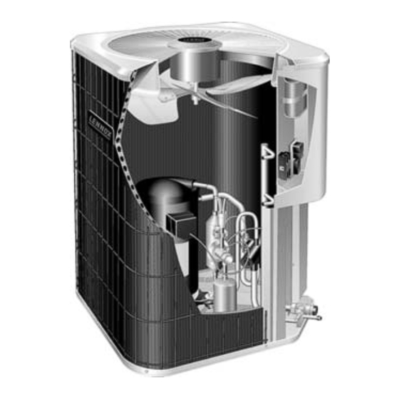
13HPD Outdoor Unit
The Lennox 13HPD Heat Pumps, which will also be
referred to in this instruction as the outdoor unit, uses
HCFC−22 refrigerant. This unit must be installed with a
matching indoor unit and line set as outlined in the Lennox
Engineering Handbook. This unit is designed for use in
check thermal expansion valve (CTXV) and fixed orifice
systems.
Page 1
. . . . . . . . . . . . . . . . . . . . . .
. . . . . . . . . . . . . . . . . . . . . . . . . . .
. . . . . . . . . . . . . . . . . . . . . . . . . . .
. . . . . . . . . . . . . . . . . . .
. . . . . . . . . . .
. . . . . . . . . . . . . . . . . . . . . . . . . . .
. . . . . . . . . . . . . . . . . . . . . . . . . . . . . .
. . . . . . . . . . . . . . . . . . . . . . . . .
. . . . . . . . . . . . . . . . . . . . . . . . .
. . . . . . . . . . . . . . . . . . . . . . . . . . .
. . . . . . . . . . . . . . . . . . . .
. . . . . . . . . . . . . . . . . . . . . . . . . . . . .
. . . . . . . . . . . . . . . . . . . . . . . .
. . . . . . . . . . . . .
505,361M
*P505361M*
Litho U.S.A.
1
1
2
2
. . . . .
4
. . . .
5
5
. . . . . . . .
6
8
9
10
11
12
14
15
17
17
18
20
22
Advertisement
Table of Contents

Related Manuals for Lennox Merit Series13HPD Units


Summary of Contents for Lennox Merit Series13HPD Units
-
Page 1: Table Of Contents
HCFC−22 refrigerant. This unit must be installed with a of July 1, 1992. Approved methods of recovery, matching indoor unit and line set as outlined in the Lennox recycling or reclaiming must be followed. Fines Engineering Handbook. This unit is designed for use in... -
Page 2: Unit Dimensions
Lennox Industries Inc. P.O. Box 799900 Each valve is equipped with a service port which has a Dallas, TX 75379−9900 factory−installed valve stem. - Page 3 DISTRIBUTOR OUTDOOR UNIT NOTE − Arrow indicate direction of refrigerant flow. REVERSING VALVE CHECK EXPANSION VALVE BI−FLOW FILTER / OUTDOOR DRIER COIL HIGH MUFFLER PRESSURE PRESSURE INDOOR UNIT LIQUID SERVICE PORT VAPOR GAUGE MANIFOLD SERVICE PORT LIQUID LINE VAPOR LINE HCFC−22 VALVE VALVE...
-
Page 4: Recovering Refrigerant From Existing System
3. Replace the stem cap and tighten as follows: With Torque Wrench: Finger tighten and then tighten per table 1. With Torque Wrench: Tighten finger tight and then tighten per table 1. Without Torque Wrench: Finger tighten and use an appropriately sized wrench to turn an additional Without Torque Wrench: Finger tighten and use an 1/12 turn clockwise as illustrated in figure 2. -
Page 5: Disconnecting And Removing Old Outdoor Unit
MANIFOLD GAUGES RECOVERY MACHINE (SEE NOTES BELOW FIGURE) (SEE NOTES (SEE NOTES BELOW BELOW FIGURE) FIGURE) SEE NOTES NOTES BELOW FIGURE) CLEAN RECOVERY CYLINDER OUTDOOR UNIT Figure 7. Installation Clearances NOTES: Figure 6. Typical Refrigerant Recovery (Method 1) Service clearance of 30 in. (762 mm) must be maintained on one of the sides adjacent to the control METHOD 2: box. -
Page 6: New Or Replacement Refrigerant Line Set
REFRIGERANT LINE SET Field refrigerant piping consists of liquid and vapor lines from the outdoor unit (braze connections) to the indoor unit coil (flare or braze connections). Use Lennox L15 (braze, non−flare) series line set, or use field−fabricated refrigerant MOUNTING lines as listed in table 2. - Page 7 ANCHORED HEAVY NYLON WIRE TIE Line set for heat pump applications can not be installed underground. For more information see the Lennox Refrigerant Piping Design and Fabrication Guidelines, or contact Lennox Technical Support Product Applications for assistance. WALL...
-
Page 8: Replacing Refrigerant Metering Device
13HPD units are used in check thermal expansion valve not be appropriate. (CTXV) and fixed orifice systems. See the indoor unit CTXV SYSTEMS installation instruction and the Lennox Engineering 1. On fully cased coils, remove the coil access and Handbook for approved metering device and application plumbing panels. -
Page 9: Brazing Connections
NOTE − The CTXV can be installed internally in coil OUTDOOR UNIT blowers, or external or internal to indoor coil only SERVICE VALVE applications. REMOVE SERVICE PORT CAP Table 4. CTXV Indoor Kits Model Kit Number 13HPD−018, −024, −030, −036 LB−85759F REMOVE PORT CORE 13HPD−042, −048... -
Page 10: Testing For Leaks
REMOVE CAP AND CORE FROM ATTACH CUT AND DEBUR BOTH SERVICE PORTS GAUGES INDOOR UNIT COIL SERVICE VAPOR LINE VALVE 13HPD UNIT SERVICE LIQUID LINE VALVE FLOW NITROGEN WRAP SERVICE NITROGEN VALVE BRAZE LINE SET Figure 17. Brazing Connections 6. Braze the line to the liquid line service valve. Turn off NOTE −... -
Page 11: Evacuating The System
5. Close the valve on the HCFC−22 cylinder and the valve NOTE − During the early stages of evacuation, it is on the high pressure side of the manifold gauge set. desirable to close the manifold gauge valve at least once to determine if there is a rapid rise in sure indicates a 6. -
Page 12: Electrical Connections
4. Install room thermostat (ordered separately) on an Electrical Connections inside wall approximately in the center of the NOTE − 24VAC, Class II circuit connections are made in conditioned area and five feet (1.5 m) from the floor. the low voltage junction box It should not be installed on an outside wall or where it can be affected by sunlight, drafts or vibrations. - Page 13 COMPRESSOR CONTACTOR CONTROL BOX READ WARNING AND NOTE CAPACITOR WARNING! − ELECTRIC SHOCK HAZARD. Can cause INJURY or DEATH. Unit must be grounded in accordance with national and local codes. NOTE − For use with copper conductors only. Refer to unit rating plate for minimum circuit ampacity and maximum DEFROST CONTROL over-current protection size.
-
Page 14: Start−Up Procedures
Delta−T Step 1. Determine the desired DT Measure entering air tempera- Temp. 24 24 24 23 23 22 22 22 20 19 18 17 16 15 of air ture using dry bulb (A) and wet bulb (B). DT is the intersecting value of entering A and B in the table (see triangle). -
Page 15: Determining Charge Method
3. Set the room thermostat to 75° to 80° and a call for 1. Recover the refrigerant from the unit. heat. This will create the necessary load for properly 2. Conduct leak check; evacuate as previously outlined. charging the system in the cooling cycle. 3. - Page 16 CHARGE USING THE APPROACH METHOD − 5. The difference between the ambient and liquid OUTDOOR TEMPERATURE > 65_F (18_C) temperatures should match the approach values listed in table 8. If the values do not agree with the those The following procedure is intended as a general guide and listed in table 8, add refrigerant to lower the approach is for use on expansion valve systems only.
-
Page 17: System Operation
System Operation Defrost System The 13HPD defrost system includes two components: a The outdoor unit and indoor blower cycle on demand from defrost thermostat and a defrost control board (DCB). the room thermostat. When the thermostat blower switch DEFROST THERMOSTAT is in the ON position, the indoor blower operates The defrost thermostat as illustrated in figure 27 is located continuously. -
Page 18: Maintenance
DS1 and DS2 LED Codes Table 10. Defrost Control Board Diagnostic LED Mode Green LED (DS2) Red LED (DS1) No power to control Normal operation / Simultaneous Slow FLASH power to control 90 DEFAULT Anti-short cycle lock- Alternating Slow FLASH TEST Low pressure switch Slow FLASH... - Page 19 Table 11. Defrost Control Board (DCB) Inputs, Outputs and Configurable Settings DCB Label or Purpose Function Location Description TEST Test Mode See Test Mode on page 22 for further details. The DCB as illustrated in figure 28 has valid selections which are: 30, 60, and 90°F (−1, 16 and 32°C).
-
Page 20: Homeowner Information
Cleaning of the outdoor unit’s coil should be performed 1. Air Filter Ask your Lennox dealer to show you where by a trained service technician. Contact your dealer your indoor unit’s filter is located. It will be either at the... - Page 21 In Emergency Heat mode, all heating demand is PROGRAMMABLE THERMOSTATS satisfied by auxiliary heat; heat pump operation is Your Lennox system controlled locked out. After a six-hour warm-up period, the programmable thermostat. These thermostats provide the thermostat can then be switched to the HEAT setting added feature of programmable time-of-day setpoints for and normal heat pump operation may resume.
-
Page 22: Start−Up And Performance Checklist
Start−Up and Performance Checklist Customer Address Indoor Unit Model Serial Outdoor Unit Model Serial Notes: START−UP CHECKS Refrigerant Type: Rated Load Amps Actual Amps Rated Volts Actual Volts Condenser Fan Full Load Amps Actual Amps: COOLING MODE Vapor Pressure: Liquid Pressure: Supply Air Temperature: Ambient Temperature: Return Air Temperature:...