Dukane iQ Series Quick Start Manual
Multi-point controller with ethernet and net i/o
Hide thumbs
Also See for iQ Series:
- User manual (178 pages) ,
- Application note (16 pages) ,
- Operating instructions (4 pages)

Related Manuals for Dukane iQ Series


Summary of Contents for Dukane iQ Series
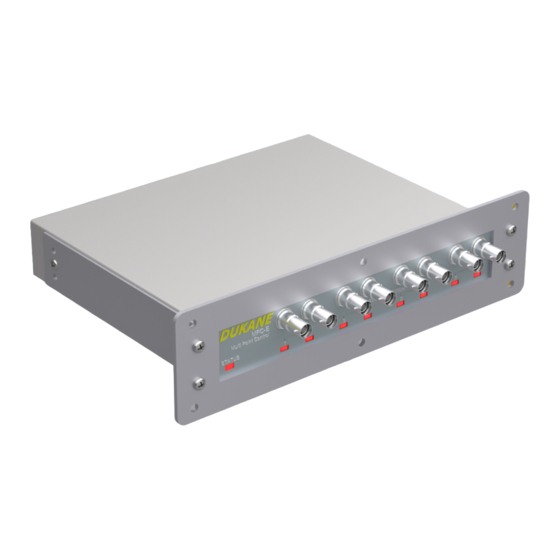
- Page 1 Series MPC-E Multi-Point Controller with Ethernet and Net I/O QUICK START GUIDE www.dukane.com ussales@dukane.com Globe-Am ENVELOPE...
- Page 2 The information contained in this manual is distributed on an “As is” basis, without warranty. While every precaution has been taken in the preparation of this manual, Dukane shall not have any liability to any person or entity with respect to any liability, loss, or damage caused or alleged to be caused directly or indirectly by the instructions contained in this manual, or by the hardware products described herein.
-
Page 3: Table Of Contents
Model Numbers ......... 23 Regulatory Agency Compliance Contacting Dukane Dukane ISO Certification... -
Page 4: Section 1 - Introduction
SECTION Introduction... -
Page 5: General User Information
Warning statements point out safety issue or an operator protection issue. conditions or practices that could result in personal injury or loss of life. Condition Electrical Hearing or Practice Hazard Protection iQ Series, MPC-E User’s Manual... -
Page 6: Unpacking
Below is a link to the blank front panel AiM generator manual: https:/ /documents.dukane.com/Manuals/403-611.pdf Below is a link to the color front panel AiM generator manual: https:/ /documents.dukane.com/Manuals/403-610.pdf Below is a link to the AiM Automation Interface Guidelines: https:/ /documents.dukane.com/AppNote/AN525.pdf iQ Series, MPC-E User’s Manual... -
Page 7: Mpc-E Module Panel Mount Installation
For panel mounted modules, use Figure 1-1 below to determine the size of the cut needed for your equipment panel. Make the appropriate cut and install the MPC-E module securing the mounting flange to the equipment panel before continuing with the cable connections. Figure 1-1 MPC-E Module Cutout Guide iQ Series, MPC-E User’s Manual... -
Page 8: Section 2 - Health And Safety
SECTION Health and Safety iQ Series, MPC-E User’s Manual... -
Page 9: General Considerations
Keep the Cover On - Do not remove any equipment cover unless directed to an ultrasonic assembly system. A do so by Dukane. Hazardous electrical voltages are present which could cause typical iQ Series system consists of injury. -
Page 10: Plastics Health Notice
After the cables have been securely should be made to the U.S. Department of Labor concerning OSHA regulations connected and the connections and for a particular plastic prior to processing with Dukane ultrasonic equipment. cable routing checked a final time, the power may be restored. -
Page 11: Section 3 - Standard Connections
SECTION Standard Connections iQ Series, MPC-E User’s Manual... -
Page 12: Power Grounding
MPC-E module. This helps suppress electrical interference or radio frequency interference (RFI) that is common in an industrial environment. CAUTION If you have any questions about the grounding your equipment and/or the electrical box, contact a qualified electrician. iQ Series, MPC-E User’s Manual... -
Page 13: Connecting Cables
4. Connect the included ground wire from the PE grounding stud to a protective earth ground. 5. Connect ultrasound coax cables from the MPC-E probe outputs to the ultrasonic probes. Figure 3-1 MPC-E Rear Panel View iQ Series, MPC-E User’s Manual... -
Page 14: Port Descriptions
USB Input Connector Connect a Windows PC to this port using the included USB cable in order to use Dukane’s PC interface tool, iQ CommanderTM. This tool allows the user to easily update firmware, set the MPC-E name, perform diagnostics, and view lifetime statistics. - Page 15 (black carbon deposits) on either the ultrasound Ultrasound Input J1 connectors or the ultrasonic cable connectors. This is the MPC-E Module ultrasonic input. This is connected to the generator J1 output connector. iQ Series, MPC-E User’s Manual...
-
Page 16: Section 4 - Led Descriptions
SECTION LED Descriptions iQ Series, MPC-E User’s Manual... -
Page 17: Status" Led Color Patterns
Transducer voltage exceeded the Orange - Blinking U116 (Over Voltage Overload) maximum expected value. Generator was not ready when cycle start Purple - Blinking Cycle Start Rejected was attempted. Table 4-1 STATUS LED Color Pattern Descriptions iQ Series, MPC-E User’s Manual... -
Page 18: Probe" Led Color Patterns
The MPC-E detects ultrasonics, but the generator does not indicate it is not idle. Green - Blinking MPC-E Power Not OK MPC-E is unconnected or unpaired to a NET I/O connection. Table 4-2 STATUS LED Color Pattern Descriptions Figure 4-1 MPC-E Front Panel View iQ Series, MPC-E User’s Manual... -
Page 19: Section 5 - Pairing
SECTION Pairing iQ Series, MPC-E User’s Manual... -
Page 20: Installing Iq Commander Tm
/update.dukane.com 1. Download the installation file from (http:/ /update.dukane.com) and save to the desired location on the PC. 2. Double-click on the installation file. 3. Once prompted, click on “Next >” on the “Welcome to the InstallShield Wizard for iQ Commander”... -
Page 21: Pairing With Iq Commander Tm
Connect the Windows PC with iQ Commander installed to the USB port of the iQ Auto Plus using a standard USB cable (Dukane part number 200-1906). Connect the Ethernet port of the iQ Auto Plus to the NET I/O port of the MPC-E using a shielded CAT 5e or better Ethernet cable (Dukane part number 200-1961-XXX). -
Page 22: Pairing With The Push Button
Connect the Ethernet port of the iQ Auto Plus to the NET I/O port of the MPC-E using a shielded CAT 5e or better Ethernet cable (Dukane part number 200-1961-XXX). 1. Verify the STATUS LED color is White indicating the MPC-E is unpaired. If the STATUS LED is White, then proceed to step 3. -
Page 23: Section 6 - Specifications
SECTION Specifications iQ Series, MPC-E User’s Manual... -
Page 24: Mpc-E Outline Drawing
MPC-E Outline Drawing Figure 6-1 400-2687 MPC-E Outline Drawing NOTE: Find additional outline drawings at the following link below: https:/ /support .dukane .com/layouts/Index/Ultrasonic Welding iQ Series, MPC-E User’s Manual... -
Page 25: Operating Environment
5% to 95% non–condensing @ 0°C to +30°C Weight Standard Model: 5 pounds (2.3 kg) Shipping: Add 3.5 pounds (1.6 kg) to unit weight for packing materials. DC Power Requirements Operate the MPC-E within these guidelines +24VDC @ 0.25A Max. iQ Series, MPC-E User’s Manual... -
Page 26: Model Numbers
HI POWER WITH DISTANCE (8 POINTS) NOTE: Model numbers with a “L” are for 30kHz frequencies and above and a maximum of 600 Watts. Model numbers with a “H” are for a maximum of 2600 Watts. iQ Series, MPC-E User’s Manual... -
Page 27: Regulatory Agency Compliance
The iQ MPC-E complies with these standards as verified by TÜV Rheinland. on specific model numbers. Tested to Underwriters Laboratories: UL 61010–1, IEC 61010-1 CAN / CSA National Standards of Canada: CAN/CSA C22.2 No. 61010–1–12 iQ Series, MPC-E User’s Manual... - Page 28 Contacting Dukane Identify Equipment When contacting Dukane about a service–related problem, be prepared to give the following information: • Model number, line voltage and serial number. • Fault/error indicators from the Status LED and/or iQ Commander • Software version displayed in the “MAIN” tab in iQ Commander •...
- Page 29 Dukane chose to become ISO certified in order to demonstrate to our customers our continuing commitment to being a quality vendor. By passing its audit, Dukane can assure you that we have in place a well–defined and systematic approach to quality design, manufacturing, delivery and service. This certificate reinforces Dukane’s status as a quality vendor of technology and products.
- Page 30 Please refer to our website at: www.dukane.com/contact-us to locate your local representative.