Table of Contents
Advertisement
Advertisement
Table of Contents

Related Manuals for Volvo Penta TAD1240GE


Summary of Contents for Volvo Penta TAD1240GE
- Page 1 OPERATOR’S MANUAL Generating set and industrial engines 12 liter (EDC III)
- Page 2 This is not by chance. After more than 90 years of producing engines the name Volvo Penta has come to symbolize reliability, technical ingenuity, first-class perfor- mance and longevity.
-
Page 3: Table Of Contents
Before starting ............ 19 Effect on engine ..........52 Starting procedure EDCIII ........20 Operation ............53 Volvo Penta start lock ......... 21 Start-up under extreme cold ........ 22 Fault codes ............55 Never use starting fluid ........23 Start-up with helper batteries ....... 23 Technical data ............ -
Page 4: Safety Information
If there is anything that you are unclear on or unsure about even af- ter reading the book, please contact your Volvo Penta dealer for assistance. This symbol is used in the instruction book and on the product to let you know that it con- cerns safety information. -
Page 5: Safety Instructions For Operation And Maintenance
Hair, fingers, loose-fitting clothing or a dropped tool severe injury. Volvo Penta recommends that all ser- can get caught in rotating parts causing severe injury. vice work that requires that the engine be running be If the engine has been delivered without protective co- assigned to an authorized Volvo Penta repair facility. - Page 6 Safety information Safety instructions for operation and maintenance (cont.) Lifting the engine Batteries When lifting the engine use the lifting eyes that are Batteries contain and develop oxyhydrogen gas, espe- mounted on the engine. Always make sure that the cially while charging. Oxyhydrogen gas is easily flam- lifting device is in good condition and has sufficient mable and very explosive.
- Page 7 Safety information Cooling system Electric welding Avoid opening the coolant filler cap when the engine is Remove the positive and negative cables from the warm. Steam or hot coolant can squirt out causing batteries. Next, remove all connections to the genera- burns.
-
Page 8: Introduction
Introduction This instruction book has been compiled to give you the best possible use of your Volvo Penta industrial engine. It contains the information you need to operate and take care of the engine in a safe and correct manner. We the- refore ask you to read the instruction book carefully and to learn to handle the engine, controls and additional equipment in a safe manner before you start the engine. -
Page 9: Certified Engines
AB Volvo Penta may otherwise completely or partially deny warranty claims. Contact your Volvo Penta dealer if you do not have a Warranty and Service book as well as a customer copy of the warranty card. -
Page 10: Presentation
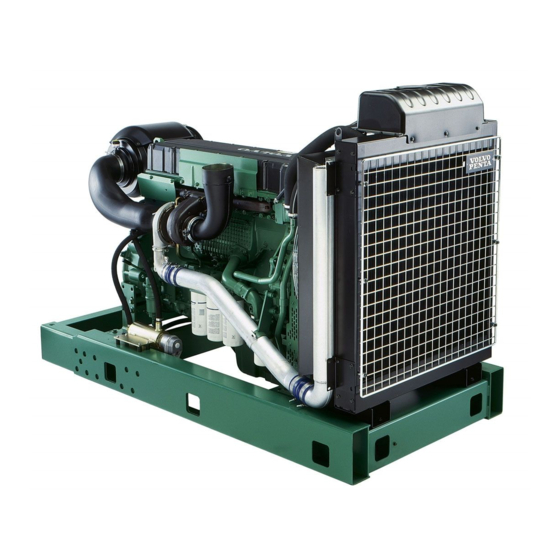
Presentation TAD1240GE, TAD1241GE/VE, TAD1242GE/VE and TWD1240VE are inline, direct-injected, 6-cylinder industrial diesel engines. They are equipped with electronically controlled fuel management, turbochargers, intercoolers and thermostati- cally regulated cooling systems and electronic RPM regulation. Technical description Engine and cylinder block Lubrication system –... -
Page 11: Identification Numbers
E Computer kit number F Product number The above plate shows: (K) Engine family Explanation of engine designation: (J) Swept volume Ex. TAD1240GE/TWD1240VE (A) Engine designation T – Turbo (F1) Valve clearance, inlet A – Air-to-air Charge air cooler (F2) Valve clearance, outlet W –... -
Page 12: Orientation
Presentation Orientation The picture shows TAD1240GE, TAD1241GE and TAD1242GE variants. 1. Expansion tank 2. AC generator 3. Control unit 4. Air filter 5. Starter motor 6. Fuel pre-filter with water sensor 7. Fuel filter with fuel pressure sensor 8. Oil dipstick 9. -
Page 13: Edc Iii
EDC III stands for ”Electronic Diesel Control” and is an electronic system with CAN (Controller Area Network) communication for diesel engine management. The system was developed by Volvo Penta and includes such pa- rameters as fuel management and diagnostic functions. -
Page 14: Instrument Edc Iii
Presentation Instrument, EDC III NOTE! All instruments are accessories. CIU - Control Interface Unit The CIU is the “translator” between the control unit and the customer’s own control panel. The CIU has two serial communication links, a fast one and a slow one. -
Page 15: Dcu (Display Control Unit)
Presentation DCU (Display Control Unit) The DCU (Diesel Control System) control panel is available as an optional accessory for the EMS (Engine Man- agement System) electronic control system. The DCU is a digital instrument panel which communicates with the engine control unit. DCU has several functions, such as: engine control, monitoring, diagnostics and parameter setting. - Page 16 Presentation Menus There are several sub-menus under each main menu. There is not space for all the menu choices on the display. To scroll through the menus, use the “7” and “9” buttons on the display. Press the “SEL” button, no. “8”...
- Page 17 Presentation Preheat manual activation of pre-heating. When it is activated, the EMS system senses when started if pre-heating is needed. For automatic pre-heating, please refer to the “Setup” / “Pre-heat on ignition” menu. The pre-heating time is adjusted to suit the engine temperature, and can last for up to 50 seconds both before and after starting.
- Page 18 Presentation Setup parameter setting in the engine’s control systems. Dif- ferent menus appear under “Customer parameter”, de- pending on whether you select “Versatile” or “Genset” from “Set application”. The parameters that can be set / selected (choice is made with the SEL button) are: •...
- Page 19 Presentation Customer parameter / Genset • Primary engine speed - selection of engine speed, 1500 or 1800 rpm. • Preheat on ignition - activation of automatic pre- heating. The engine control system senses if pre- heating is needed and activates it directly when switched on.
- Page 20 Presentation Display setting settings for the display. Adjustment is done with the “7” and “9” buttons, please refer to the DCU panel in the illustration. • Set contrast (%) - display contrast adjustment. • Set backlight time (sec) - sets the time (in sec- onds) for background illumination in the display.
-
Page 21: Starting The Engine
Starting the engine Make a habit of always visually checking the engine and engine compartment prior to starting the engine. This will help you to quickly notice if any abnormal conditions have occurred or are occurring. Check also to verify that the instruments show normal values after start-up. -
Page 22: Starting Procedure Edciii
Starting the engine Starting method EMS 2 The pre-heating time is adjusted to suit the engine temperature, and can last for up to 50 seconds both before and after starting. The starter motor connection time is maximized to 30 seconds. After that, the starter motor circuit is cut for 80 seconds to protect the starter motor against over- heating. -
Page 23: Volvo Penta Start Lock
Starting the engine Volvo Penta start lock: 1. Turn the key to the ”I” position and check the indicator lamps. 2. Position”II”. Pre-heating is activated (pre-heating is an option). Wait until the pre-heating indicator lamp goes out. Pre-heating time is dependent upon engine temperature. -
Page 24: Start-Up Under Extreme Cold
Pre-heat the coolant by using a separately mounted electric engine heater. In extreme cases it can be ne- cessary to use a diesel-powered engine heater. Con- sult your Volvo Penta dealer. IMPORTANT! Make sure that the cooling sys- tem is filled with a glycol mixture. See the chapter ”Maintenance, cooling system”. -
Page 25: Never Use Starting Fluid
Starting the engine Never use starting spray WARNING! Never use starting spray or other similar substances to help start an engine. This could cause an explosion in the intake tract. This poses a risk of injury. Start with booster batteries WARNING! Batteries (especially booster batteries) contain oxyhydrogen gas that is very explosive. -
Page 26: Operation
Operation Correct operation technique is very important for both fuel economy and engine life. Always let the engine warm up to normal operating temperature before operating at full power. Avoid sudden throttle openings and operation at high engine speeds. Operation at low load Checking instruments Avoid long-term operation at idle or at low load, since Check all instruments directly after starting, and then... -
Page 27: Shutting Down The Engine
Stopping the engine In case of extended time between uses the engine should be run until warm at least once every 14 days. This pre- vents corrosion of the engine. If the engine will not be used for more than two months preservation should be performed. See the chapter ”Storage”. -
Page 28: Maintenance Schedule
Maintenance schedule General Your Volvo Penta engine and its equipment are built to provide a high degree of reliability and a long useful life. They are built to have the minimum possible effect upon the environment. Preventative maintenance according to the maintenance schedule and use of original Volvo Penta parts will preserve these qualities and help to avoid un- necessary operational disturbances. -
Page 29: Newly Rebuilt Engine
Maintenance Every 800th operational hour / at least every 12th month • Charge air pipes, check for leaks ..............page 28 • Fuel pre-filter, change filter element ...............page 43 • Fuel filter, change ..................page 42 Fuel system, purging ..................page 44 •... -
Page 30: Maintenance
Maintenance This chapter contains general technical information and instructions detailing how the recommended maintenance should be performed. Read carefully through the instructions before starting the task. The time frames for when each maintenance point should be performed are given in the previous chapter: Maintenance schedule. WARNING! Read through the safety instructions for maintenance and service work in the chapter: Safety in- formation, before starting to work. - Page 31 Maintenance Drive belts, check/adjust. Check and adjustments should be done when the drive belts are warm. The drive belt to the generator should be able to press in 3-4 mm between the drive belt pulleys. The drive belt to the generator must be adjusted manually but the other drive belt is automatically adjusted.
- Page 32 Maintenance 6. Mount the new drive belt and tighten it with the tightening screws (3). The play should be 3 mm for new belts and 3-4 mm for old belts. The play is measured where the drive belts are at their long- est between pulleys.
- Page 33 It may not be cleaned or reused. IMPORTANT! Under continuous operation the filter should be checked every 8 hours. For operation in extremely dirty environments such as coal mines and stone crushers a special filter is available (not sold by Volvo Penta).
-
Page 34: Lubrication System
Maintenance Lubrication system Oil change intervals can vary between 50–600 hours depending upon the grade of the oil and the sulfur content of the fuel. Note that the oil change intervals may never exceed a period of 12 months. If change intervals longer than those provided are desired, the condition of the oil must be checked by the manu- facturer of the oil by regular testing. - Page 35 Maintenance Oil level, check and add The oil level should be within the marked area on the dipstick and should be checked daily before the first start. Add oil using the filler opening on the side of the engine. Check that the correct level is reached. Wait a few minutes so that the oil has time to run down into the oil pan.
- Page 36 Maintenance Oil filter/Bypass filter, change WARNING! Hot oil can cause severe burns. 1. Clean the oil filter housing. 2. Remove all oil filters using appropriate filter wrenches (1). 3. Clean the sealing surface on the filter housing, making sure that no gasket residue remains. 4.
-
Page 37: Cooling System
The coolant should contain ethylene glycol of a good quality with a suitable chemical consistency for an adequate protection of the engine. Using anti-corrosion aditive exclusively is not permitted in Volvo Penta’s engines. Never use water by itself as coolant. - Page 38 (18°F). (Using 60 % glycol lowers the freezing point to -54 °C (65°F)). Never mix more than 60 % concentrate (Volvo Penta Coolant) in the cooling liquid, this will give reduced cooling effect and increase the risk of overheating, and will give reduced freezing protection.
- Page 39 NOTE! Do not open the pressure cap. 1. Open the filler cap (1). NOTE! Use only Volvo Penta recommended coolant and mixtures. 2. Mix the correct amount of coolant ahead of time (see the table below) so that it can be assured that the system has been filled.
- Page 40 2. Open all of the drain valves. Drain the coolant from the radiator. Use drain hose that can be orded from Volvo Penta, the drain cock (P) is located under the radiator. 3. Make sure that all coolant runs out. Deposits may exist just inside of the cocks/plugs that must be cleaned away.
- Page 41 Maintenance Cooling system, flushing 1. Drain the cooling system, see “Draining, cooling system”. NOTE! If the cooling system is flushed regularly, for example by draining and refilling with rust-preventative fluid, a smaller amount of flushing additive or simple rinsing with clean water can be sufficient. 2.
- Page 42 Maintenance Coolant filter, change 1. Turn the valve (1) 90° to stop the flow through the coolant filter. 2. Remove the coolant filter using an appropriate fil- ter wrench. Make sure that no residue from the old gasket remains on the housing. 3.
-
Page 43: Fuel System
Maintenance Fuel system Only use fuel of the recommended grade according to the fuel specification below. Always make sure to maintain a high level of cleanliness when fueling and when working with the fuel system. All work involving the engine’s unit injectors must be performed by an authorized service location. WARNING! Risk of fire. - Page 44 Maintenance Fuel filter, change NOTE! Do not fill the new fuel filter with fuel prior to mounting, there is a risk that impurities can be intro- duced into the system causing operational interrup- tions or damage. WARNING! Fuel filter replacement should be carried out on a cold engine to avoid the risk of fire caused by fuel spilling onto hot surfaces.
- Page 45 Maintenance Fuel pre-filter with water monitor, change 1. Clean the area around the fuel filter. 2. Disconnect the water monitor(1). 3. Drain the fuel filter, see ”Fuel system, draining”. 4. Remove the fuel filter using an appropriate filter wrench. NOTE! If the entire filter unit with the water separator is not going to be changed the water monitor should be moved to the new fuel filter.
- Page 46 Maintenance Fuel system, bleeding 1. Clean around the air bleeding nipples on the cylin- der head and the fuel filter bracket. 2. Bleed the fuel system at the fuel filter. Connect a transparent plastic hose between the bleed nipple (1) and a collection vessel. 3.
-
Page 47: Electric System
The fuse is placed adjacent to the engine control unit on the engine’s left side. Note: The engine will stop if the fuse (+) blows out. If the fuse blows out often an authorized Volvo Penta repair facility should be contacted to investigate the cause of the overload. - Page 48 Maintenance Batteries, maintenance WARNING! Fire and explosion risk. Batteries may never be exposed to open flame or sparks. WARNING! Never confuse the plus and minus poles of the batteries. Risk of causing sparks and explosion. WARNING! Battery electrolytes is strongly corrosive.
- Page 49 Maintenance Batteries, charging WARNING! Explosion risk. During charging oxyhydrogen gas is formed. Short-circuits, open flame or sparks can cause a powerful explosion. Ventilate well. WARNING! Battery electrolyte is strongly corrosive. Protect eyes, skin and clothing. Always use safety glasses and gloves. In case of skin contact, wash with soap and large quantities of water.
- Page 50 Maintenance Electric component schematic Coolant level sensor Control unit RPM sensor, camshaft Fuel pressure alarm Diagnostic outlet 8-pin connector Programming connection 23-pin connector Boost pressure/intake temperature sensor Coolant temperature sensor Extra stop Starter motor Main relay Starter motor, relay Generator RPM sensor, flywheel Safety fuse 10A Water monitor, fuel filter...
-
Page 51: Preparation For Storage
It is important that this be done correctly and that no part of it be forgotten. We have therefore created a checklist covering the most important points. Before the engine is taken out of service for an extended period an authorized Volvo Penta service facility should perform a check. -
Page 52: Preparation After Storage
Preparation for storage Preparation for use after storage • • Remove any covers from the engine, air filter and Close the drain valves and replace any drain exhaust pipe. plugs. • • Fill the engine with the proper grade of lubricating Check the coolant levels. -
Page 53: Troubleshooting
A number of symptoms and possible causes for engine problems are described in the table below. Always contact your Volvo Penta dealer if problems occur that you are not able to solve on your own. WARNING! Read through the safety instructions for maintenance and service work in the chapter ”Safety in- formation”... -
Page 54: Diagnostic Function
Diagnostic function The diagnostic function monitors and checks that the EMS 2 system functions normally. The diagnostic function has the following tasks: • Discover and localize malfunctions • Notify that malfunctions have been discovered • Give advice in fault finding Fault code If the diagnostic function discovers a malfunction in •... -
Page 55: Operation
Diagnostic function Operation Reading fault cause via the DU (Display When a malfunction has occurred and the diagnostic system has generated one or more fault codes, these Unit) are read out differently, depending on the equipment Depending on the severity of the faults, one of the fol- used. - Page 56 Diagnostic function Reading fault codes via the diagnostic Reading fault codes via ”Easy Link” in- lamp on the instrument panel, CIU strument (only with CIU) When the system has discovered a malfunction, the When the system has discovered a malfunction, the diagnostic lamp starts to flash.
-
Page 57: Fault Codes
Fault codes WARNING! Read through the safety advice for care and maintenance work in the ”Safety information” chap- ter before you start work. NOTE! Reading the fault codes below, such as Code 2.1, PID 97 means that 2.1 is the flashing code indicated by the diagnostic lamp. - Page 58 Fault codes Code 2.6, PID / SPN 190. Engine speed Code 3.1, PID / SPN 100. Oil pressure sensor Cause: Cause: • Engine speed too high. • Short circuit to positive (+) or earth (ground) (–). Reaction: • Open circuit. •...
- Page 59 Fault codes Code 3.4, PID / SPN 106/102, Code 3.7, PID / SPN 175. Oil temperature sensor Charge pressure sensor Cause: Cause • Shorted to plus (+) or minus (-). • Short circuit to positive (+) or earth (ground) (–). •...
- Page 60 Fault codes Code 4.1 PPID 260. Oil pressure alarm lamp, Code 4.4 PPID 264. Overspeed alarm lamp, Connected to Stand-Alone Interface Connected to Stand-Alone Interface Reason: Reason: • • Short circuit to negative (-). Short circuit to negative (-). • •...
- Page 61 Fault codes Code 4.8, PPID 6/ SPN 520195. Stop input EDC Code 5.4, PID 45/ SPN 626. Preheating relay Cause: Cause: • Short circuit to negative (-). • Short circuit to positive (+) or earth (ground) (–). • Open circuit. •...
- Page 62 Fault codes Code 6.4, PPID 231 / SPN 639, Data link (CAN), Code 5.9, PID / SPN 98. Oil level sensor Cause: Cause: • Shorted to plus (+) or minus (-). • Faulty data link (CAN), CIU. • Break. Reaction: Reaction: •...
- Page 63 Fault codes Code 7.2, SID 2 / SPN 652 Code 6.9, PID / SPN 158, Battery voltage, CIU Injector, cylinder #2 Cause: Cause: • Short circuit to negative (-). • Electrical fault. • Faulty alternator. • Faulty compression or injector. •...
- Page 64 Fault codes Code 7.4, SID 4 / SPN 654 Code 7.6, SID 6 / SPN 656 Injector, cylinder #4 Injector, cylinder #6 Cause: Cause: • Electrical fault. • Electrical fault. • Faulty compression or injector. • Faulty compression or injector. Reaction: Reaction: •...
- Page 65 Fault codes Code 9.3, SID 232 / SPN 620 Code 9.9, SID 240 / SPN 639. Memory fault Power supply to sensor Cause: Cause: • Memory fault in engine management system. • Shortcut. Reaction: • Fault in sensor. • Engine might not start. Reaction: Remedy: •...
-
Page 66: Technical Data
Technical Data General Type designation ........TAD1240GE TAD1241-42GE TAD1241-42VE TWD1240VE Number of cylinders ......... Cylinder diameter ........131 mm (5.16") 131 mm (5.16") 131 mm (5.16") 131 mm (5.16") Stroke ............150 mm (5.91") 150 mm (5.91") 150 mm (5.91") 150 mm (5.91") -
Page 67: Fuel System
Technical data Fuel system Injection order Injection order ............1-5-3-6-2-4 Feed pump Feed pressure after fuel filter at 1000 RPM, min............350 kPa (51 psi) Feed pressure after fuel filter at full load, min.............. 350 kPa (51 psi) Overflow valve Opening pressure ............ -
Page 68: Electric System
Electrical system System voltage ............24 V Alternator: voltage/max. current ..........28 V/60 A power approx............1700 W Battery capacity ............2 serial-connected 12 V, max. 152 Ah Battery electrolyte density at +25°C: fully charged battery ..........1.28 g/cm (1.24 g/cm the battery discharges at ........ - Page 69 Notes ..............................................................................................................................................................................................................................................................................................................................................................................................................................................................................................................................................................................................................................................................................................................................................................................................................................................................................................................................................................................................................
- Page 70 Notes ..............................................................................................................................................................................................................................................................................................................................................................................................................................................................................................................................................................................................................................................................................................................................................................................................................................................................................................................................................................................................................
- Page 71 ✂ Yes please, I would like an operator’s manual in English at no charge. Publication number: 7745138 Post or fax this coupon to: Document & Distribution Center Name Order Department ARU 2, Dept. 64620 Address SE-405 08 Göteborg Sweden Fax: +46 31 545 772 Orders can also be placed via the Internet: http://www.volvopenta.com/...
- Page 72 ✂ Sí gracias, deseo recibir gratuitamente un libro de instrucciones en español. Número de publicación: 7741215 Franquear o enviar fax a: Document & Distribution Center Nombre Order Department ARU 2, Dept. 64620 Dirección SE-405 08 Göteborg Suecia Fax: +46 31 545 772 El pedido puede hacerse también por internet: http://www.volvopenta.com/...
- Page 73 ✂ Ja graag, Ik wil kosteloos een instructieboek in het Nederlands ontvangen. Publicatienummer: 7741218 Stuur of fax de coupon naar: Document & Distribution Center Naam Order Department ARU 2, Dept. 64620 Adres SE-405 08 Göteborg Zweden Fax: +46 31 545 772 U kunt ook bestellen via internet: http://www.volvopenta.com/...
- Page 74 ✂ Íáé, Èá Þèåëá Ýíá áíôßôõðï ôïõ åã÷åéñéäßïõ ÷ñÞóçò óôçí áããëéêÞ ãëþóóá ÷ùñßò êáìéÜ ÷ñÝùóç. Áñéèìüò Ýêäïóçò: 7741221 Ôá÷õäñïìÞóôå áõôü ôï êïõðüíé ¼íïìá óôçí ðáñáêÜôù äéåýèõíóç Þ óôåßëôå ôï ìå öáî óôïí ðáñáêÜôù áñéèìü öáî: Äéåýèõíóç Document & Distribution Center Order Department ARU 2, Dept.