Table of Contents
Advertisement
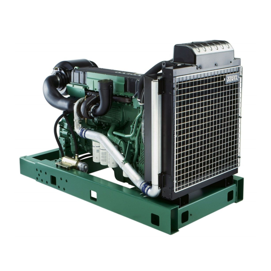
VOLVO PENTA GENSET ENGINE
TAD1241GE
1500 rpm, 354 kW (481 hp) – 1800 rpm, 387 kW (526 hp)
The TAD1241GE is a powerful, reliable
and economical Generating Set Diesel
Engine built on the dependable in-line six
design.
Durability & low noise
Designed for easiest, fastest and most
economical installation. Well-balanced to
produce smooth and vibration-free opera-
tion with low noise level.
To maintain a controlled working tem-
perature in cylinders and combustion
chambers, the engine is equipped with
piston cooling. The engine is also fitted
with replaceable cylinder liners and valve
seats/guides to ensure maximum durabil-
ity and service life of the engine.
Low exhaust emission
The state of the art, high-tech injection
and charging system with low internal
losses contributes to excellent combus-
tion and low fuel consumption.
The TAD1241GE complies with EU
Stage 2 and TA-Luft -50% exhaust emis-
sion regulations.
Easy service & maintenance
Easily accessible service and mainte-
nance points contribute to the ease of
service of the engine.
Technical description:
Engine and block
– Optimized cast iron cylinder block with opti-
mum distribution of forces without the block
being unnessarily heavy.
– Wet, replaceable cylinder liners
– Piston cooling for low piston temperature
and reduced ring temperature
– Tapered connecting rods for reduce risk of
piston cracking
– Crankshaft induction hardened bearing
surfaces and fillets with seven bearings for
moderate load on main and high-end bear-
ings
– Case hardened and nitrocarburized trans-
mission gears for heavy duty operation
– Keystone top compression rings for long
service life
– Viscous type crankshaft vibration dampers
to withstand single bearing alternator tor-
sional vibrations
– Replaceable valve guides and valve seats
– Over head camshaft and four valves per cyl-
inder
Features
– Maintained performance, air temp 40°C
– Tropical cooling system (55°C)
– Fully electronic with Volvo Penta EDC III
– Dual frequency switch (between 1500 rpm and 1800 rpm)
– High power density
– Emission compliant
– Low noise levels
– Gen Pac configuration
Lubrication system
– Full flow oil cooler
– Full flow disposable spin-on oil filter, for ex-
tra high filtration
– The lubricating oil level can be measured
during operation
– Gear type lubricating oil pump, gear driven
by the transmission
Fuel system
– Non-return fuel valve
– Electronic Unit Injectors
– Fuel prefilter with water separator and wa-
ter-in-fuel indicator / alarm
– Gear driven low-pressure fuel pump
– Fine fuel filter with manual feed pump and
fuel pressure switch
– Fuel shut-off valve, electrically operated
Cooling system
– Air to air intercooler
– Coolant filter as standard
– Gear driven, maintenance-free coolant
pump with high degree of efficiency
– Efficient cooling with accurate coolant con-
trol through a water distribution duct in the
cylinder block. Reliable sleeve thermostat
with minimum pressure drop
Turbo charger
– Efficient and reliable turbo charger
– Extra oil filter for the turbo charger
Electrical system
– Electronical Diesel Control III (EDCIII), an
electronically controlled processing system
which optimizes engine performance. It also
includes advanced facilities for diagnostics
and fault tracing
– Three different ways for the customer to
connect his controls and instrument to the
engine. CAN SAE J1939 interface, CIU
(Control interface unit) and Stand alone
connections.
– Sensors for oil pressure, oil temp, boost
pressure, boost temp, coolant temp, fuel
temp, water in fuel, fuel pressure and two
speed sensors.
Advertisement
Table of Contents

Related Manuals for Volvo Penta TAD1240GE


Summary of Contents for Volvo Penta TAD1240GE
- Page 1 Stage 2 and TA-Luft -50% exhaust emis- – Tropical cooling system (55°C) sion regulations. – Fully electronic with Volvo Penta EDC III – Dual frequency switch (between 1500 rpm and 1800 rpm) Easy service & maintenance – High power density Easily accessible service and mainte- –...
- Page 2 TAD1241GE Technical Data General Standard equipment Engine Gen Pac Engine designation ................ TAD1241GE Engine No. of cylinders and configuration ............in-line 6 Automatic belt tensioner • • Method of operation ................4-stroke Lift eyelets • • Bore, mm (in.) ..................131 (5.16) Flywheel Stroke, mm (in.) ..................
-
Page 3: Design And Operation
EDC III, ”Electronic Diesel Control”, is an electronic system with CAN communication for diesel engine manage- ment. The system is developed by Volvo Penta and covers fuel management, diagnostic function, etc. The sys- tem consists of a control module, six unit injectors, a number of sensors that provide information to the control module, and a data link connector for diagnostics and functionality checks. - Page 4 Group 23 EDC III Design and operation Calculation of fuel quantity The amount of fuel injected into a cylinder is calcula- ted by the control module. The calculation gives the amount of time the fuel valve is closed (as fuel is in- jected into the cylinder when the fuel valve is closed).
-
Page 5: Component Description
Group 23 EDC III Design and operation Component description The digits after the headings refer to ”Component dia- gram and location”. Water monitor, fuel pre-filter (19) The monitor is located on the bottom of the fuel pre- filter. Its role is to guard against water in the fuel system. The monitor consists of two copper pins between which resistance is measured. -
Page 6: Coolant Temperature Sensor
Group 23 EDC III Design and operation Tachometer sensor, flywheel (18) This sensor is located on the left-hand side of the fly- wheel housing. The tachometer sensor on the flywheel is an inductive sensor. It reads the crankshaft position and engine speed using grooves in the flywheel. -
Page 7: Electronic Control Unit (Ecu)
Group 23 EDC III Design and operation Coolant level monitor (1) This monitor is located in the expansion tank. Its task is to detect if the coolant level in the cooling system (expansion tank) is too low. The monitor con- sists of a contact that can be actuated magnetically. -
Page 8: Unit Injectors
Group 23 EDC III Design and operation Unit injectors (20) The unit injectors are located under the valve cover, mounted in the cylinder head. The engine’s fuel need is analyzed up to 100 times per second (depending on engine speed). The quantity and timing of fuel injection into the engine are control- led completely electronically via the unit injectors’... - Page 9 Group 23 EDC III Design and operation Component diagram and location 1. Coolant level monitor 11. Control unit (ECU) 2. Tachometer sensor, camshaft 12. Fuel pressure monitor 3. Connection, diagnostic tool* 13. 8–pin connection (Data bus) 4. Programming plug* 14. 23–pin connection (Stand alone) 5.
-
Page 10: Alarm Values
Group 23 EDC III Limit values Limit values Limit values, electronic control unit (ECU) TAD1240GE, TAD1241-42GE/VE Alarm values The maximum permissible values for charge air and coolant temperatures, for example, can be adjusted with the parameter setting tool and can thus vary within alarm limits. -
Page 11: Alarm Limits
Alarm limits: Coolant temperature: Alarm lamp lights Engine is switched off Engine output 50% Standard value Volvo Penta 98°C / 208°F 100°C / 212°F Parameter setting (can be set by the customer) 95–101°C / 203-214°F +2°C / 36°F over the alarm value NOTE: Engine protection can be switched off. - Page 12 Group 23 EDC III Limit values Limp-home values (emergency control values) The control unit uses these bases value to be able to run the engine if a technical error arises in the system or its peripheral equipment, sensors, etc. The following values (Limp-home values) are stored in the control unit: Charge air temperature +45°C / 113°F...
-
Page 13: Repair Instructions
Group 23 EDC III Repair instructions Repair instructions When working with EDC III Follow the instructions below so as not to damage the control unit of the EDC system: • Never cut off the main current when the engine is running. •... - Page 14 Group 23 EDC III Repair instructions Electronic Control unit (ECU), replacement 1. Cut off power to the engine. 2. Remove the fuel cooling coil and fuel line clamps from the control unit. Bend aside the cooling coil. 3. Disconnect the cable glove from the control unit. Press in the catch (1) and push the cable glove (2) upwards.
- Page 15 Group 23 EDC III Repair instructions Start with booster batteries WARNING! Be sure to have good ventilation. The batteries build oxyhydrogen gas, which is very flammable and explosive. A short-circuit, open flame or spark could cause an explosion. WARNING! Never confuse the position of the cables on the battery.
-
Page 16: Functionality Check
• User information is included in the program. • Contact your Volvo Penta dealer to order software. • The role of the diagnostic function is to detect and localize disturbances in the EDC III system, protect the engine and ensure that the machine remains in working order during serious disturbances. -
Page 17: Fault Detection
A number of symptoms and possible causes for engine problems are described in the table below. Always contact your Volvo Penta dealer if problems occur that you are not able to solve on your own. WARNING! Read through the safety instructions for maintenance and service work in the chapter ”Safety in- formation”... -
Page 18: Diagnostic Function
Response: TAD1240–42GE/VE: RPM maintained. TWD1240VE: The engine goes to idle. Idle or freezing of RPM can be set using the Volvo Penta Parameter Tool. If the diagnosis button’s indicator blinks 1. Reduce RPM to idle. - Page 19 Group 23 EDC III Diagnostic function NOTE: If the warning lamps and other instruments show normal function and the control is working nor- mally, the operator can choose to continue operating and remedy the disturbance later. If the engine is swit- ched off, certain error codes could disappear.
- Page 20 Group 23 EDC III Diagnostic function Error codes EDC III WARNING! Read the safety instructions for maintenance and service work in the chapter ”Safety informa- tion” before starting to work. NOTE: The readout of the error codes below, such as 175 Code 2.1, means that 175 is read using the diagnostic tool. 2.1 is the blink code that is shown on the instrument box’s diagnostic lamp.
- Page 21 Group 23 EDC III Diagnostic function 102 Code 2.5 24 Code 2.7 Cause: RPM sensor, camshaft. No signal. Cause: RPM potentiometer connected to the engine control unit (ECU). Short to negative (-). Response: The engine takes longer than normal to start.
- Page 22 Group 23 EDC III Diagnostic function 181 Code 3.1 26 Code 3.2 Cause 1: Oil pressure sensor. Short to positive (+). Cause: Charge air temperature sensor. Short to negative (-). Response: None. Response: None. Corrective action: Corrective action: • Check that the wiring to the oil pressure sensor is •...
- Page 23 Group 23 EDC III Diagnostic function 67 Code 3.4 185 Code 3.7 Cause: Charge air pressure sensor. Short to positive (+). Cause: Oil temperature sensor. Short to negative (-). Response: The engine smokes more than it usually Response: None. does when accelerating/under loading. Corrective action: Corrective action: •...
- Page 24 Group 23 EDC III Diagnostic function 35 Code 4.2 221 Code 4.3 Cause: Alarm for high coolant temp. Linked to Stand Cause: Lamp to indicate operation. Short to Alone interface. Short to negative (-). negative (-). Response: Alarm lamp lights constantly. Response: The indicator lamp shines constantly.
- Page 25 Group 23 EDC III Diagnostic function 203 Code 4.5 42 Code 4.6 Cause: Low coolant alarm. Circuit interruption. Cause: Start relay on starter motor. Short to negative (-). Response: Alarm lamp does not work. If the circuit is interrupted during start-up, diagnostics are deacti- Response: Engine will be started ->...
- Page 26 Group 23 EDC III Diagnostic function 109 Code 4.8 209 Code 5.3 Cause: Stop input engine control unit (ECU). Cause: Stop input on CIU. Short to negative (-). Short to negative (-). Response: The engine can only be stopped using the Response: The engine can only be stopped using emergency stop on the engine.
- Page 27 Group 23 EDC III Diagnostic function 74 Code 5.4 31 Code 6.1 Cause: Preheating relay. Connection interruption Cause: High coolant temperature. Response: Preheating cannot be activated. Response: TAD1240–42GE: Limited engine output (if this protective feature has not been disabled by the Corrective action: parameter setting tool).
- Page 28 Group 23 EDC III Diagnostic function 38 Code 6.5 106 Code 6.5 Cause Datalink (CAN) error, engine control module Cause: Datalink error (CAN). (EMS). Response: Engine not running -> The engine cannot Response: Engine not running: the engine cannot be be started.
- Page 29 Group 23 EDC III Diagnostic function 111 Code 7.1 115 Code 7.1 Cause: Unit injector cylinder #1. Electronic error. Cause: Unit injector cylinder #1. Electronic error. Response: The engine runs on 5 cylinders, sounds Response: The engine runs on 5 cylinders, sounds uneven and has decreased performance.
- Page 30 Group 23 EDC III Diagnostic function 123 Code 7.2 130 Code 7.3 Cause: Unit injector cylinder #2. Electronic error. Cause: Unit injector cylinder #3. Electronic error. Response: The engine runs on 5 cylinders, sounds Response: The engine runs on 5 cylinders, sounds uneven and has decreased performance.
- Page 31 Group 23 EDC III Diagnostic function 133 Code 7.3 140 Code 7.4 Cause: Unit injector cylinder #3. Electronic error. Cause: Unit injector cylinder #4. Electronic error. Response: The engine runs on 5 cylinders, sounds Response: The engine runs on 5 cylinders, sounds uneven and has decreased performance.
- Page 32 Group 23 EDC III Diagnostic function 144 Code 7.4 151 Code 7.5 Cause: Error in compression or the unit injector on cy- Cause: Unit injector cylinder #5. Electronic error. linder #4. Response: The engine runs on 5 cylinders, sounds Response: Cylinder balance is adversely affected -> uneven and has decreased performance.
- Page 33 Group 23 EDC III Diagnostic function 154 Code 7.5 161 Code 7.6 Cause: Error in compression or the unit injector on cy- Cause: Unit injector cylinder #6. Electronic error. linder #5. Response: The engine runs on 5 cylinders, sounds Response: The engine runs on 5 cylinders, sounds uneven and has decreased performance.
- Page 34 Group 23 EDC III Diagnostic function 164 Code 7.6 254 Code 9.8 Cause: Error in compression or the unit injector on cy- Cause: Controller failure, CIU linder #6. Response: The engine cannot be started, if the engi- Response: Cylinder balance is adversely affected -> ne is running ->...
- Page 35 Group 23 EDC III Diagnostic function 34 Code - 64 Code - Cause: The diagnostic lamp (linked to the Stand Alone Cause: Voltage feed to sensor. Short to negative (-). interface). Short to positive (+). Response: Several error codes for sensor error. Response: The diagnostic lamp does not light during Corrective action: a lamp test.
- Page 36 Group 23 EDC III Diagnostic function 187 Code - 231 Code - Cause: Memory error in the engine control module Cause: Input for preheating request. Short to negative (-). (EMS). Response: Pre-heating can not be activated. Response: Engine will not start. Corrective action: Corrective action: •...
- Page 37 Group 23 EDC III Electronic fault detection Electronic fault detection General Functionality check of lines and connectors Check the following before star ting electronic fault detection: First check that the fuse is not loose. • Error codes Use multimeter • Fuel level and filter 9510060-8 to take a reading from the wiring.
- Page 38 Group 23 EDC III Electronic fault detection Interruption Check the following: • Look for oxidation, which can deteriorate Chafed or worn lines or loose connections could be possible causes of error. the contact in the connections. • Check that the cable shoes are not damaged, that Use the wiring diagram to check which wiring harnes- ses are used for the function.
- Page 39 Group 23 EDC III Electronic fault detection Splicing electrical cable for cable glove Special tools: 951 2636, 9999324 Repair kit: 1078054 1. Disconnect the cable glove from the control module. See ”Control module, replacement”. Remove the cable glove in such a way that the cable to the pin that is to be replaced is accessible.
-
Page 40: Checking The Coolant Temperature Sensor
Group 23 EDC III Electronic fault detection Checking the combined Checking the coolant sensor for charge air pressure/ temperature sensor temperature Checking charge air pressure 1. Switch off the engine 2. Disconnect the connector from the charge air 1. Disconnect the connector and remove the pressure sensor and connect 4-pin adapter sensor from the engine. - Page 41 Group 23 EDC III Electronic fault detection Checking water monitor, fuel Checking the camshaft and pre-filter flywheel sensors 1. Red cable in connector. 2. Yellow cable in connector. 3. Black cable in connector. 1. Disconnect the connector and remove the water The tachometer sensors for the camshaft and the fly- monitor from the fuel pre-filter.
- Page 42 Group 23 EDC III Electronic fault detection Checking the combined sensor Checking the coolant level for oil pressure/temperature sensor Checking the function of oil pressure Empty the coolant from the expansion tank. 1. Switch off the engine Warning! NEVER open the expansion tank’s 2.
- Page 43 Group 23 EDC III Electronic fault detection Fault detection on unit injectors Error symptoms The engine runs unevenly or has decreased perfor- mance. Error causes The above error symptoms can have several causes: • False sensor signals • Worn piston rings •...
-
Page 44: Carbon Brushes
Group 23 EDC III Electronic fault detection Fault detection on starter motor and lines General If the voltage level of the battery is under 24.7V as measured from the battery, the starter motor does not have enough power to rotate the engine at normal speed. - Page 45 Group 23 EDC III Electronic fault detection Functionality check of relays Multimeter 9510060-8 is used for fault detection. Two different symbols are used to represent the line connection. Symbol 1 indicates an interruption or ex- tremely high resistance (~). The multimeter does not emit an alarm.
- Page 46 Group 23 EDC III Electronic fault detection Fault detection on the generator First remove the generator so that measurement points are accessible. 1. Pry loose the plastic cover of the generator with a screwdriver. 2. Remove the regulator’s four screws. 3.
- Page 47 Group 23 EDC III Electronic fault detection Carbon brushes The length of carbon brushes is measured between the contact surface and the brush holder. If the size of the projecting portion is less than 0,2’’ or if the brushes are damaged, they must be replaced. NOTE: When soldering, make sure that the solder does not penetrate too far in the line to the brushes.
- Page 48 Group 23 EDC III Electronic fault detection Checking positive output diodes 1. Set the multimeter for diode measurement. 2. Connect the negative test probe to B+ and the po- sitive test probe to each of the three stator win- dings. 3.
- Page 49 Group 23 EDC III Electronic fault detection Checking negative output diodes 1. Set the multimeter for diode measurement. 2. Connect the negative test probe to B- and the po- sitive test probe to each of the three stator win- dings. 3.
- Page 50 Group 23 EDC III Electronic fault detection Checking excitation diodes 1. Set the multimeter for diode measurement. 2. Connect the negative test probe to D+ and the po- sitive test probe to each of the three stator win- dings. 3. Take readings of the three stator windings. 4.
- Page 51 Group 23 EDC III Electronic fault detection Checking stator windings 1. Set the multimeter for diode measurement. 2. Connect the test probes between the phase con- nections. 3. Take three readings. 4. The instrument should show the same value for all three readings.
- Page 52 Group 23 EDC III Electronic fault detection Checking the rotor Set the multimeter for diode measurement. Connect the test probes to the slip rings. The instrument reading should be nonexistent or very weak. At the same time, check that the slip rings are not burned or otherwise damaged.
-
Page 53: Electrical System
Always attach welding clamps to the part that is to be circuits, a Volvo Penta charge distributor can be welded as close to the welding area as possible. The mounted on the standard generator (accessory). -
Page 54: Electrical System, Overview
Group 23 EDC III Electrical system Electrical system, overview TWD1240VE Stand alone TWD1240VE with CIU, CAN based SAE J1939... - Page 55 Group 23 EDC III Electrical system TWD1240VE Power pack TAD1240–42GE with CIU, CAN based SAE J1939 TAD1241–42VE with CIU, CAN based SAE J1939...
- Page 56 Group 23 EDC III Electrical system TAD1240–42GE Stand alone TAD1241–42VE Stand alone...
- Page 57 Group 23 EDC III Electrical system...
- Page 58 Group 23 EDC III Electrical system...
- Page 59 Group 23 EDC III Electrical system Cable colors Wiring diagram, Control Interface Unit (CIU) Blue = Pink LBL = Light blue = Red 1. Key breaker operating power Brown SB = Black (15+) LBN = Light brown VO = Violet 2.
- Page 60 Group 23 EDC III Electrical system Wiring diagram, Control Interface Unit (CIU) – Cable colors Power pack Blue = Pink LBL = Light blue R = Red 1. Activating operating power, contact (15+) Brown SB = Black 2. RPM potentiometer 3.
- Page 61 Group 23 EDC III Index Index About the Service Manual ........5 Our common responsibility ........6 Certified engines ............ 5 PC diagnostics program ........25 Check/fault detection of components ....49 Component description, sensors and monitors ..14 Reading out error codes ........27 Component diagram and location ......