Table of Contents
Advertisement
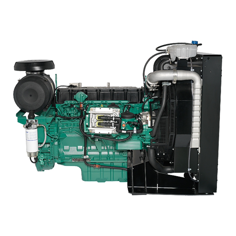
VOLVO PENTA INDUSTRIAL DIESEL
TAD734GE
250kW (340 hp) at 1500 rpm, 263 kW (357 hp) at 1800 rpm, acc. to ISO 3046
The TAD734GE is a powerful, reliable
and economical Generating Set Diesel
Engine built on the dependable in-line six
design.
Durability & low noise
Designed for easiest, fastest and most
economical installation. Well-balanced to
produce smooth and vibration-free opera-
tion with low noise level.
To maintain a controlled working tem-
perature in cylinders and combustion
chambers, the engine is equipped with
piston cooling. The engine is also fitted
with replaceable cylinder liners and valve
seats/guides to ensure maximum durabil-
ity and service life of the engine.
Low exhaust emission
The state of the art, high-tech injection
and charging system with low internal
losses contributes to excellent combus-
tion and low fuel consumption.
The TAD734GE complies with EU Stage
2 exhaust emission regulations.
Easy service & maintenance
Easily accessible service and mainte-
nance points contribute to the ease of
service of the engine.
Technical description
Engine and block
– Optimized cast iron cylinder block with opti-
mum distribution of forces
– Piston cooling for low piston temperature
and reduced ring temperature
– Drop forged steel connecting rods
– Crankshaft hardened bearing surfaces and
fillets for moderate load on main and big-
end bearings
– Keystone top compression rings for long
service life
– Replaceable valve guides and valve seats
– Three PTO positions at flywheel end
– Lift eyelets
– Flywheel housing with connection acc. to
SAE 2
– Flywheel for flexplate
– Fixed integrated radiator front engine sus-
pension
– Transport brackets, rear
Lubrication system
– Full flow cartrigde insert filter
– Rotary displacement oil pump driven by the
crankshaft
– Deep front oil sump
– Oil filler on top
– Oil dipstick, short in front
– Integrated full flow oil cooler, side-mounted
Features
– Electronic governing, EMS2
– CAN bus communication
– Compact design for the power class
– High power to weight ratio
– Emission compliant
– Noise optimized engine design
– Dual speed
Fuel system
– Common rail
– Gear driven fuel feed pump
– Six hole fuel injection nozzles
– Electronic governor
– Fuel prefilter with water separator
– Fine fuel filter of cartridge insert type
Intake and exhaust system
– Connection flange for exhaust line
– Waste gate turbo charger, centre low with
exhaust flange
– Two-stage air filter, with cyclon
– Heater flange in charge air inlet (with relay)
Cooling system
– Belt driven, maintenance-free coolant pump
with high degree of efficiency
– Efficient cooling with accurate coolant con-
trol through a water distribution duct in the
cylinder block
– Reliable thermostat with minimum pressure
drop
– Pusher fan
Electrical system
– Engine Management System 2 (EMS 2), an
electronically controlled processing system
which optimizes engine performance. It also
includes advanced facilities for diagnostics
and fault tracing
– The instruments and controls connect to the
engine via the CAN SAE J1939 interface,
either through the Control Interface Unit
(CIU) or the Display Control Unit (DCU).
The CIU converts the digital CAN bus signal
to an anolog signal, making it possible to
connect a variety of instruments. The DCU is
a control panel with display, engine control,
monitoring, alarm, parameter setting and di-
agnostic functions. The DCU also presents
error codes in clear text.
– Sensors for oil pressure, boost pressure,
boost temp, exhaust temp, coolant temp,
water in fuel, fuel pressure and two speed
sensors.
Advertisement
Table of Contents

Related Manuals for Volvo Penta TAD734GE


Summary of Contents for Volvo Penta TAD734GE
- Page 1 VOLVO PENTA INDUSTRIAL DIESEL TAD734GE 250kW (340 hp) at 1500 rpm, 263 kW (357 hp) at 1800 rpm, acc. to ISO 3046 The TAD734GE is a powerful, reliable and economical Generating Set Diesel Engine built on the dependable in-line six design.
-
Page 2: Standard Equipment
TAD734GE Technical Data Standard equipment General Engine Engine designation ................TAD734GE Automatic belt tensioner • No. of cylinders and configuration ............in-line 6 Lift eyelets • Method of operation ................4-stroke Flywheel Bore, mm (in.) ..................108 (4.25) Flywheel housing with conn. acc. to SAE 2 •... - Page 3 OPERATOR’S MANUAL 9 Liter (EMS 2) Volvo TAD734GE...
- Page 4 All engines are equipped with electronically controlled fuel management (EMS 2), turbocharger, charge air cooler, thermostatically controlled cooling systems and electronic speed control. TAD950VE, TAD951VE have TAD952VE are also equipped with internal EGR (Exhaust Gas Recircula- tion). 47702660 03-2013 © AB VOLVO PENTA...
- Page 5 EMS (Engine Management System) EMS (Engine Management System) is an electronic system with CAN communication (Controller Area Network) for diesel engine control. The system was developed by Volvo Penta and includes fuel control and diagnostic function. Input signals Output signals...
-
Page 6: Instruments And Controls
Scroll downwards in menus SPEED - . Reduces engine rpm SEL. Selects in menus SPEED +. Increases engine rpm Scroll upwards in menus STOP. Stops the engine 10 ESC. Return to previous menu selection 47702660 03-2013 © AB VOLVO PENTA... -
Page 7: Engine Data
Coolant temperature (°C) • Charge air temperature (°C) Oil pressure (kPa) • • Oil temperature (°C) • Engine hours (h) Battery voltage (V) • • Fuel consumption (l/h) • Instantaneous fuel consumption (trip fuel) (l) 47702660 03-2013 © AB VOLVO PENTA... - Page 8 The fault codes are shown as text on the display. • Scroll through the fault list with the arrow keys. Trip Data reset resets trip data, such as fuel consumption. • Press the SEL button to reset trip data 47702660 03-2013 © AB VOLVO PENTA...
-
Page 9: Customer Parameter / Versatile
For activation, refer to Gov- ernor droop in the main menu. • Oil temp warning limit (°C) - setting alarm limit for oil temperature. • Coolant temp warning limit (°C) - setting alarm limit for coolant temperature. 47702660 03-2013 © AB VOLVO PENTA... -
Page 10: Throttle Input Setting
- engine rpm is controlled by an external unit. Set idle voltage (V) - idle voltage level setting. • • Set max voltage (V) - full throttle voltage level set- ting. 47702660 03-2013 © AB VOLVO PENTA... -
Page 11: Display Setting
DCU hardware Id - DCU part number. • DCU software Id - DCU software part number. • DCU dataset1 Id - DCU data set 1 part number. • DCU dataset2 Id - DCU data set 2 part number. 47702660 03-2013 © AB VOLVO PENTA... -
Page 12: Display Modes
In the display modes Engine, Trip and Graph, it is pos- sible to adjust the contrast. Press button 5 outside the menu and then + (button 4) or – (button 3) to adjust the contrast. 47702660 03-2013 © AB VOLVO PENTA... - Page 13 The information is shown as graphs. Press button 4 repeatedly to choose what information will be shown. The time interval is set in the Configuration menu. If the connection is broken there will be a straight line in the display. 47702660 03-2013 © AB VOLVO PENTA...
-
Page 14: Configuration Menu
- PRESSURE; kPa, PSI - VOLUME; LITRE, GAL, Imperial GAL. Fuel rate is adjusted according to volume unit, L/H, GAL/H, IGAL/H. - TEMPERATURE; °C, °F Alarm Status List of active alarms, refer to Fault Handling page 34 47702660 03-2013 © AB VOLVO PENTA... - Page 15 EEPROM – number of write on EEPROM VERS – software version number CHK – Flash memory checksum PART No – Volvo software part number SOURCE – source of received data LABLE – Allocated Label on the same bus. 47702660 03-2013 © AB VOLVO PENTA...
-
Page 16: Easy Link Instruments
- Tachometer / hours counter (fault codes are also displayed on the tachometer display when the diag- nostic button is pressed) - Coolant temperature - Oil pressure - Oil temperature - Battery voltage - Alarm panel - Turbo pressure 47702660 03-2013 © AB VOLVO PENTA... -
Page 17: Before Starting
Move the engine speed control to idle, and open the disengageable clutch/gearbox if installed. IMPORTANT! P0002078 Never break the circuit with the main switch while the engine is running, as this may damage the alternator. 47702660 03-2013 © AB VOLVO PENTA... -
Page 18: Starting The Engine
(7),press SEL-button (8) Never race the engine when it is cold. 4 In the pre-heater menu, press the SEL-button (8) to select pre-heating. 5 Press the START- button (2). 47702660 03-2013 © AB VOLVO PENTA... -
Page 19: Starting In Extreme Cold
Never Use Start Spray WARNING! Never use start spray or similar agents to start an engine. This may cause an explosion in the inlet mani- fold. Danger of personal injury. P0002080 47702660 03-2013 © AB VOLVO PENTA... -
Page 20: Starting Using Auxiliary Batteries
Risk of arcing. Do not bend over any of the batteries either. 4 Remove the cables in the reverse order. IMPORTANT! The ordinary cables to the standard batteries must not be loosened on any condition. 47702660 03-2013 © AB VOLVO PENTA... -
Page 21: Operation
This is done by means of CAN signals to the instrument. More information about fault codes and fault tracing can be found in the chapter. Fault Handling page 30. 47702660 03-2013 © AB VOLVO PENTA... -
Page 22: Operation At Low Load
5 minutes. • Run the engine at full load for about 4 hours once a year. In this way carbon deposits in the engine and exhaust system are given the chance to burn up. 47702660 03-2013 © AB VOLVO PENTA... -
Page 23: Before Engine Shutdown
NOTICE! If there is a risk of frost, the coolant in the cooling system must have sufficient frost protection. Refer to the chapter Maintenance page 52. A poorly-charged battery can freeze and burst; refer to Battery, Charging page 60. 47702660 03-2013 © AB VOLVO PENTA... -
Page 24: Extra Stop
For location of the extra stop, please refer to Location of Sensors page 43. WARNING! Working with or going close to a running engine is a safety risk. Watch out for rotating components and hot surfaces. 47702660 03-2013 © AB VOLVO PENTA... -
Page 25: Fault Handling
Fault Tracing A number of symptoms and possible causes of engine malfunctions are described in the table below. Always contact your Volvo Penta dealer if any problems occur which you cannot solve by yourself. IMPORTANT! Read through the instructions for care and mainte- nance in the Safety precautions for boat operation chapter before starting work. - Page 26 21 Clogged charge air cooler 22 Oil level too high 23 Alternator drive belt slipping 24 Water entry into engine 25 High back pressure in exhaust system 26 Break in Pot+ cable to pedal 47702660 03-2013 © AB VOLVO PENTA...
-
Page 27: Diagnostic Function
VODIA). All fault codes and fault messages can be found in the Fault Code Register together with information about cause, reaction and actions, for further information see chapter Fault Code Register. 47702660 03-2013 © AB VOLVO PENTA... - Page 28 NOTICE! When the first fault code reappears, all fault codes have been read off. If the diagnostics button is pressed after the fault has been rectified and the fault codes have been erased, code 1.1 “No fault” will be displayed. 47702660 03-2013 © AB VOLVO PENTA...
- Page 29 6 Press button 4 for at least three seconds to view SPN and FMI codes. 7 Press EXIT to leave the fault list. Alarms that are acknowledged and rectified are automatically erased from the list. 47702660 03-2013 © AB VOLVO PENTA...
-
Page 30: Display Control Unit (Dcu)
5 Press ESC to leave the fault list. NOTICE! To get to the fault list when no fault codes are set, press the SEL button and select Diagnos- tics from the menu. 47702660 03-2013 © AB VOLVO PENTA... -
Page 31: Erasing Fault Codes
2 must be acknowledge and read out every time the engine is switched on. If the diagnostic button is depressed after the fault has been corrected and fault code deleted, the code 1.1,No fault, will show. 47702660 03-2013 © AB VOLVO PENTA... -
Page 32: Fault Code Register
SAE J1708 Data Link 9.2/- SAE J1939 Data Link +5V sensor supply 9.3/- 3, 4 Inlet Air Temperature 5.4/- 3, 4, 5 Program memory 9.9/- 2, 12 Controller error 9.9/- (EMS) 8, 12 9.8/- (CIU) 47702660 03-2013 © AB VOLVO PENTA... - Page 33 Thermostat bypass valve 2988 3, 4, 5 Exhaust gas temperature sensor #1 3241 0, 7, 4, 5 Sensor Supply Voltage #1 (+5V DC) 3509 3, 4 Sensor Supply Voltage #2 (+5V DC) 3510 3, 4 47702660 03-2013 © AB VOLVO PENTA...
- Page 34 Diagnostic request switch input Oil pressure warning lamp status 4.1/- Coolant level warning lamp status 4.5/- Diagnostic lamp status Run indication lamp status 4.3/- Over speed indication lamp status 4.4/- Coolant temperature warning lamp output 4.2/- 47702660 03-2013 © AB VOLVO PENTA...
-
Page 35: Maintenance Schedule
Maintenance Schedule Your Volvo Penta engine and its equipment are designed for high reliability and long life. It is built so as to have minimal environmental impact. If given preventive maintenance, according to the maintenance schedule, and if Volvo Penta original spares are used, these properties are retained and unnecessary malfunctions can be avoided. - Page 36 Air Filter, Tank Breather ● Air Filter, Compressor ● Every 4000 hours At least every (month) Belt Tensioner ● Drive Belts ● Coolant (green) ● Every 8000 hours At least every (month) Coolant VCS (yellow) ● 47702660 03-2013 © AB VOLVO PENTA...
-
Page 37: Maintenance
Maintenance This chapter describes the most common maintenance items, see Service program for service intervals. NOTICE! Service points which are not described here must be performed by authorized Volvo Penta workshop. CAUTION! Read the chapter on Maintenance before starting work. It contains instructions on how to carry out maintenance and service operations in a safe and correct manner. -
Page 38: Location Of Sensors
5 Charge air pressure / Intake manifold temperature 13 Preheater with preheater relay 6 Coolant temperature sensor 14 Camshaft sensor 7 Main relay 15 Flywheel sensor 8 Diagnosis connector 2-pin: TAD940–43VE, TAD940–941GE 6-pin: TAD950–51VE 47702660 03-2013 © AB VOLVO PENTA... -
Page 39: Engine, General
• In continuous operation, the filter should be checked every 8 hours. For operations in extremely dirty environments such as coal mines and rock crushing mills, special air filters must be used. P0015863 47702660 03-2013 © AB VOLVO PENTA... -
Page 40: Charge Air Pipe, Leakage Check
8 Lift the 1/2” wrench in the belt tensioner (2) and install the new water pump drive belt. 9 Install the belt guards. 10 Install the fan guard and fan ring round the cooling fan. 11 Start the engine and do a function check. 47702660 03-2013 © AB VOLVO PENTA... -
Page 41: Drive Belt, Change
8 Lift the 1/2" wrench and install the new drive belt. P0015862 9 Install the belt guards. 10 Install the fan guard and fan ring round the cooling fan. 11 Start the engine and do a function check. 47702660 03-2013 © AB VOLVO PENTA... -
Page 42: Lubrication System
(the STOP side of the dipstick) and when it is running (the OPERATING side of the dipstick). Never fill past the MAX limit on the oil dipstick. Only use Volvo Penta recommended oils; refer to Tech- nical Data page 65. •... -
Page 43: Engine Oil Change
6 Top up with engine oil, start the engine and let it run for 20-30 seconds. P0015866 7 Turn off the engine, check the oil level and top up as required. 8 Check sealing round the oil filters. 47702660 03-2013 © AB VOLVO PENTA... -
Page 44: Fuel System
4 Lubricate the seal with diesel fuel and install the new fuel filter. Tighten the fuel filter in accordance with the instructions on the fuel filter. 5 If necessary, vent the fuel system, please refer to Bleeding the Fuel System page 51. 47702660 03-2013 © AB VOLVO PENTA... -
Page 45: Fuel Pre-Filter, Change
Then tighten a fur- P0015868 ther half turn, no more. 7 Connect the cable to the water trap sensor. 8 If necessary, vent the fuel system, please refer to Bleeding the Fuel System page 51. 47702660 03-2013 © AB VOLVO PENTA... -
Page 46: Draining Condensate, Fuel System
No venting nipples need be opened. 4 Start the engine and allow it to run at a fast idle for about 10 minutes. 5 Carry out a leakage and function check. 47702660 03-2013 © AB VOLVO PENTA... -
Page 47: Cooling System
Volvo Penta Coolant VCS must have a yellow decal with the text VOLVO COOLANT VCS on the expansion tank. • The two types of Volvo Penta coolant may never be mixed with each other as this will affect the anti-cor- rosion properties. •... -
Page 48: Coolant, Mixing
This mixture prevents against internal corrosion, cavi- tation and bursts due to freezing down to -28°C (-18°F) Volvo Penta Coolant (green). -24°C (-11°F) Volvo Penta Coolant VCS (yellow). At 60% glycol concentration, the freezing point is low- ered to -54°C (-65°F) Volvo Penta Coolant (green). -
Page 49: Coolant Level, Checking And Topping Up
If a heating unit is connected to the engine cooling system, the heat control valve must be opened and the installation vented during filling. 5 Stop the engine after about an hour and check the coolant level; top off as necessary. 47702660 03-2013 © AB VOLVO PENTA... -
Page 50: Coolant Draining
Remove guards as necessary, to access the radiator. Clean with water and a mild detergent. Use a soft brush. Be careful not to damage the radiator vanes. Reinstall removed parts. IMPORTANT! Do not use a pressure washer. 47702660 03-2013 © AB VOLVO PENTA... -
Page 51: Coolant Filter, Change
55. 2 Put a hose into the expansion tank filling hole and flush with clean water, as specified by Volvo Penta– refer to section Water quality in Technical Data page 67 until the water draining out is com- pletely clear. - Page 52 8 below. 8 When the cooling system is completely free from contamination, close the drain taps and plugs. 9 Fill up with Volvo Penta recommended coolant, fol- lowing the instructions in the chapters entitled Maintenance page 52and Coolant Level, Checking and Topping Up page 54.
-
Page 53: Electrical System
The circuit breaker is located on the left-hand side of the engine Location of Sensors page 43. The engine stops if the fuse trips. If the circuit breaker trips frequently, an authorized Volvo Penta workshop should be contacted to investigate the cause of the overload. -
Page 54: Battery Maintenance
Top up with distilled water as required. After filling, the battery should be charged for at least 30 minutes by running the engine at idle. Some maintenance-free batteries have special instructions, which must be followed. P0016910 47702660 03-2013 © AB VOLVO PENTA... -
Page 55: Battery Charging
• Special instructions apply to boost charging. Boost charging can shorten battery life, and should there- fore be avoided. P0002111 47702660 03-2013 © AB VOLVO PENTA... - Page 56 Before the engine is taken out of service for a long period of time, an authorized Volvo Penta workshop should check it over. Have any faults and deficiencies attended to, so that the equipment is in order, ready for the next start.
-
Page 57: Bringing Out Of Storage
2/3 diesel fuel. • Drain the engine’s conservation oil. • Vent the fuel system. • Follow the other instructions on the previous page. * Conservation oils are sold by oil companies. 47702660 03-2013 © AB VOLVO PENTA... -
Page 58: Technical Data
9.36 (571) Displacement, (inch Weight, dry, kg (lbs) 1015 (2238) 1015 (2238) 1015 (2238) 1015 (2238) Weight, wet, kg (lbs) 1065 (2348) 1065 (2348) 1065 (2348) 1065 (2348) Firing order 1-5-3-6-2-4 1-5-3-6-2-4 1-5-3-6-2-4 1-5-3-6-2-4 47702660 03-2013 © AB VOLVO PENTA... - Page 59 138 (5.43) 9.36 (571) 9.36 (571) 9.36 (571) Displacement, (inch Weight, dry, kg (lbs) 1015 (2238) 1015 (2238) 1015 (2238) Weight, wet, kg (lbs) 1065 (2348) 1065 (2348) 1065 (2348) Firing order 1-5-3-6-2-4 1-5-3-6-2-4 1-5-3-6-2-4 47702660 03-2013 © AB VOLVO PENTA...
-
Page 60: Oil Filter
DHD = Global Diesel Heavy Duty TBN = Total Base Number Viscosity Select the viscosity according to the table. The temperature values refer to stable ambient tem- peratures. * SAE 5W/30 refers to synthetic or semi-synthetic oils. 47702660 03-2013 © AB VOLVO PENTA... -
Page 61: Fuel Specification
Vegetable oil esters (Fatty Acid Methyl Esters, FAME), also called "biodiesel", are increasingly available as a blending component in diesel fuels. Volvo Penta accepts the same FAME content as in major on-road fuels EN 590 and ASTM D975; i.e. today up to 7%, without any specific additional service requirements. Please contact your Volvo Penta Dealer for futher information. -
Page 62: Water Quality
1 pc. Thermostat, opening temperature: 82 °C (179.6 °F) Coolant Volvo Penta Coolant VCS and VCS Ready Mixed (yel- low colour) are based on Organic Acid Technology, OAT. Volvo Penta Coolant and Coolant Ready Mixed (green ad y m ix ed co ol an t vc s re colour) are silicate based. - Page 63 2 pcs series connected 12V, max. 180 Ah Battery electrolyte specific gravity at +25°C: fully charged battery 1.28 g/cm (1.24 g/cm re-charge battery at 1.20 g/cm (1.20 g/cm * Note: Applies to batteries with tropical acid. 47702660 03-2013 © AB VOLVO PENTA...
-
Page 64: Identification Numbers
A Engine designation B Engine power, net, (without fan) C Max. engine speed D Main software E Dataset 1 F Dataset 2 P0002052 G Product number 1 Engine designation 2 Serial number P0015924 3 Specification number 47702660 03-2013 © AB VOLVO PENTA...