Table of Contents
Advertisement
Quick Links
Original instructions
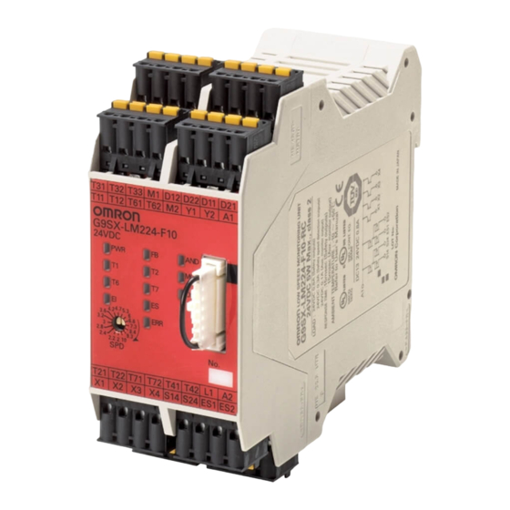
Type G9SX-LM224-F10-
Low Speed Monitoring Unit
USER'S MANUAL
English
Thank you for purchasing G9SX Flexible Safety Unit.
Please read and understand this manual before
using the products.
Keep this manual ready to use whenever needed.
Only qualified person trained in professional
electrical technique should handle G9SX.
Please consult your OMRON representative if you
have any questions or comments.
Make sure that information written in this document
are delivered to the final user of the product.
© OMRON Corporation 2008-2020 All Rights Reserved.
EU Declaration of Conformity
OMRON declares that G9SX-LM is in conformity with
the requirements of the following EU Directives:
EMC Directive 2014/30/EU
Machinery Directive 2006/42/EC
Standards
G9SX-LM is designed and manufactured in accordance
with the following standards:
EN ISO13849-1:2015 Category 3 PL d,
IEC/EN61508 SIL3,
IEC/EN61000-6-2,
UL508,
CAN/CSA C22.2 No.142
Safety Precautions
Meanings of Signal Words
The following signal words are used in this manual.
Indicates a potentially hazardous situation
which, if not avoided, will result in minor or
moderate injury, or may result in serious
WARNING
injury or death.
Additionally there may be significant
property damage.
Suitability for Use
Omron Companies shall not be responsible for conformity with
any standards, codes or regulations which apply to the
combination of the Product in the Buyer's application or use of
the Product. At Buyer's request, Omron will provide applicable
third party certification documents identifying ratings and
limitations of use which apply to the Product. This information
by itself is not sufficient for a complete determination of the
suitability of the Product in combination with the end product,
machine, system, or other application or use. Buyer shall be
solely responsible for determining appropriateness of the
particular Product with respect to Buyer's application, product
or system. Buyer shall take application responsibility in all
cases.
NEVER USE THE PRODUCT FOR AN APPLICATION
INVOLVING SERIOUS RISK TO LIFE OR PROPERTY OR IN
LARGE QUANTITIES WITHOUT ENSURING THAT THE
SYSTEM AS A WHOLE HAS BEEN DESIGNED TO ADDRESS
THE RISKS, AND THAT THE OMRON PRODUCT(S) IS
PROPERLY RATED AND INSTALLED FOR THE INTENDED
USE WITHIN THE OVERALL EQUIPMENT OR SYSTEM.
1129440-0 E
IEC/EN62061 SIL3,
IEC/EN61000-6-4,
Meaning of Alert Symbols
The following alert symbols are used in this manual.
Indicates prohibited actions.
Indicates mandatory actions.
Alert Statements
Serious injury may possibly occur due to breakdown of safety
outputs.
Do not connect loads beyond the rated value to the safety
outputs.
Serious injury may possibly occur due to loss of required
safety functions.
Wire G9SX properly so that supply voltages or voltages for
loads do NOT touch safety outputs accidentally or
unintentionally.
Serious injury may possibly occur due to damages of safety
inputs.
Apply protection circuitry against back electromotive force in
case connecting inductive loads to safety outputs.
Serious injury may possibly occur due to damages of safety
inputs.
Connect specified proximity sensors to the Rotation detection
inputs.
Cogwheel should be correctly designed and installed based
on specifications of selected proximity sensors according to '8.
Shape of Cogwheel and Setting of Proximity Sensors' in the
operating instruction and other operation manuals or related
documents supplied with the sensors. After installation of the
Cogwheel, check the operation of the system before use.
Serious injury may possibly occur due to loss of required
safety functions.
To avoid interference from surrounding metal and mutual
interference, specified proximity sensors should be correctly
designed and installed according to '8. Shape of Cogwheel
and Setting of Proximity Sensors' and operation manuals or
related documents attached to the proximity sensors.
Serious injury may possibly occur due to loss of safety
functions.
Use appropriate devices referring to the information provided
below.
Controlling
Requirements
Devices
Door
Use approved devices with Direct Opening Mechanism
interlocking
complying with IEC/EN 60947-5-1 and capable of
switch
switching micro loads of 24VDC, 5mA.
Limit switch
Enable Switch
Use approved devices complying with IEC/EN 60947-5-1.
Use devices with contacts capable of switching micro loads
of 24VDC, 5mA.
Safety Sensor
Use certified devices complying with the relevant product
standards, regulations and rules in the country where it is
used.
Consult a certification body to assess that the entire system
satisfies the required safety category level.
Use the following OMRON E2E series,
Proximity
Sensor
three-wire DC sensors (PNP).
Type E2E-X1R5F1
Type E2E-X2F1
Type E2E-X5F1
Relay with
Use approved devices with forcibly guided contacts
forcibly guided
complying with IEC 61810-3 (EN 50205).
contacts
For feedback purpose use devices with contacts capable of
switching micro loads of 24VDC, 5mA.
Contactor
Use approved devices complying with IEC/EN 60947-4-1
auxiliary contact linked with power contact (mirror contact).
For feedback purpose use devices with contacts capable of
switching micro loads of 24VDC, 5mA.
Emergency stop
Do not connect an Emergency stop switch to G9SX-LM.
switch
Other devices
Evaluate whether devices used are appropriate to satisfy
the requirements of safety category level.
- 1 -
WARNING
Type E2E-X2MF1
Type E2E-X5MF1
Type E2E-X10MF1
Advertisement
Table of Contents

Related Manuals for Omron Sti G9SX-LM224-F10 Series


Summary of Contents for Omron Sti G9SX-LM224-F10 Series
- Page 1 Suitability for Use standards, regulations and rules in the country where it is used. Omron Companies shall not be responsible for conformity with Consult a certification body to assess that the entire system any standards, codes or regulations which apply to the satisfies the required safety category level.
-
Page 2: Precautions For Safe Use
1) When using Logical AND connection inputs, set the Logical connection preset switch to 'AND' position for the units which the logical connection (14) OMRON shall not be responsible for conformity with any safety standards signal are input to. regarding to customer's entire system. - Page 3 Appearance and Explanation of Each Parts Type G9SX-LM224-F10- Feedback/Reset input Sensor power supply Rotation detection input Enable input ch1 Power Supply(+) Mode selector input Cross fault detection input G9SX-LM224-F10 Safety Input ch1 Mode selector input 24VDC Termination Connector Low-speed monitoring 4.7 5.3 3.6 4.2 T41/T42...
-
Page 4: Internal Connection
Internal Connection Type G9SX-LM224-F10- T11 T12 T21 T22 M1 M2 T61 T62 T71 T72 D12 D22 T31 T32 T33 T41 T42 Cross fault Cross fault Rotation Logical Mode Reset/ Power Enable Enable Safey Safety detection detecting detection selector Feedback supply Input Input Input... -
Page 5: Ratings And Specifications
Ratings and Specifications Ratings ITEM TYPE G9SX-LM224-F10- Rated supply voltage 24 VDC Power Operating voltage range -15% to +10% of rated supply voltage input Rated power consumption (See Note1) 5 W max. Safety input Operating voltage: 20.4VDC to 26.4VDC, Feedback/reset input Internal impedance : approx. - Page 6 Terminal arrangement and LED indicators Connecting Safety Sensors and G9SX-LM TYPE G9SX-LM224-F10- 1) When G9SX-LM is connected to a safety sensor, Terminal Y1 should be connected to 24VDC for Enable input channel. Or for Safety input channel, Terminal Y2 should be connected to 24VDC. D12 D22 D11 D21 If Terminal Y1 or Y2 is open, G9SX-LM will detect it as a...
-
Page 7: Application Examples
Application Examples G9SX-LM224-F10 (DC24V) <Guard lock Safety-door switch(Mechanical lock), Safety limit switch 2ch input / Enable 2ch input / manual reset> Lock release switch Guard Safety-door switch Motor Controller Feedback loop Devices :Safety limit switch Enable Guard :Guard lock Safety-door switch switch :Stop signal :Reset switch... -
Page 8: Control Circuit
G9SX-LM224-F10 (DC24V) <Guard lock Safety-door switch(Mechanical lock), Safety limit switch 2ch input / Enable switch 2ch input / auto reset> + G9SX-BC202 (DC24V) <Emergency stop switch 2ch input / manual reset> Feedback loop Lock release Emergency stop switch switch Guard Safety-door switch +24V T32 T33... - Page 9 Type E2E Use the following DC three-wire types, Rotation D11, Normal operation mode: To turn on Safety speed OMRON E2E series (PNP). detection outputs, pulse signals from the two detection D12, proximity sensors monitoring should be 2.0Hz or less. input...
-
Page 10: Fault Detection
The G9SX-LM can be used for PL=d and Category 3 required by EN ISO13849-1 European standard. Refer to the following link for the Safety-related characteristic data: http://www.fa.omron.co.jp/safety_6en/ However, please note that this does not mean that G9SX can be always used for this category under all similar conditions or situations. - Page 11 438A Alexandra Road # 05-05/08, Shiokoji Horikawa, Shimogyo-ku, Kyoto, 600-8530 Alexandra Technopark Singapore 119967 JAPAN SINGAPORE OMRON EUROPE B.V. (Importer in EU) PHONE: 65-6-835-3011 FAX: 65-6-835-2711 Wegalaan 67-69, NL-2132 JD Hoofddorp THE NETHERLANDS OMRON (CHINA) CO., LTD. PHONE: 31-2356-81-300 FAX: 31-2356-81-388...