Table of Contents
Advertisement
Quick Links
Instructions-Parts
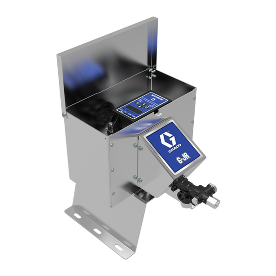
G-JR Chemical
Injection Pump
Electric pump for injecting chemicals at well sites. For professional use only.
Not approved for use in explosive atmospheres or hazardous (classified) locations.
Not recommended for use with chemicals outside of the pH range of 4-9.
See page 2 for model information, including maximum
working pressure.
Important Safety Instructions
Read all warnings and instructions in this
manual and in the Harrier
manual before using the equipment.
Save these instructions.
®
EZ-JR
3A8109A
EN
Advertisement
Table of Contents

Related Manuals for Graco G-JR


Summary of Contents for Graco G-JR
- Page 1 Instructions-Parts G-JR Chemical Injection Pump 3A8109A Electric pump for injecting chemicals at well sites. For professional use only. Not approved for use in explosive atmospheres or hazardous (classified) locations. Not recommended for use with chemicals outside of the pH range of 4-9.
-
Page 2: Table Of Contents
Repair ........13 Remove G-JR Pump ..... 13 Replace Fluid Module . -
Page 3: Warnings
Warnings Warnings The following warnings are for the setup, use, grounding, maintenance, and repair of this equipment. The exclama- tion point symbol alerts you to a general warning and the hazard symbols refer to procedure-specific risks. When these symbols appear in the body of this manual or on warning labels, refer back to these Warnings. Product-specific hazard symbols and warnings not covered in this section may appear throughout the body of this manual where applicable. - Page 4 Warnings WARNING MOVING PARTS HAZARD Moving parts can pinch, cut or amputate fingers and other body parts. • Keep clear of moving parts. • Do not operate equipment with protective guards or covers removed. • Pressurized equipment can start without warning. Before checking, moving, or servicing equipment, follow the Pressure Relief Procedure and disconnect all power sources.
-
Page 5: Component Identification
Component Identification Component Identification Access the Harrier controller (3) and other components inside the enclosure (1) by removing the lid (7) and pump cover (4). . 1 G-JR Pump Components Key: Enclosure . 2 Access to Enclosure Components G-JR Pump Module... -
Page 6: Installation
Installation Installation Grounding Accessories Install the following required accessories in the order shown in Typical Installation, page 7, using adapters as necessary. These required accessories must be sup- plied and installed by the customer before use. The equipment must be grounded to reduce the risk of static sparking and electric shock. -
Page 7: Typical Installation
Pump Outlet, 1/4 in. npt chemical injection pump. Your installation may differ Manifold Assembly (includes y-strainer) from what is shown here. The G-JR pump (A) is the only Fluid Shutoff Valve (outlet) (Required) component in F . 3 supplied by Graco. All other com- Priming Port Plug ponents are supplied by customer. -
Page 8: Choosing An Installation Location
NOTE: A Pressure Relief Valve (D) is available from Graco (see Kits and Accessories on page 18) and can 4. If you have a mounting configuration that requires be connected back to the tank or directly to the inlet side installation in a manner different than depicted in of the pump. -
Page 9: Motor Electrical Connections
Installation Motor Electrical Connections The AC and DC models both have pre-wired controllers. The power sources and connections differ as follows: • For AC models (25T651), simply plug the power cord (18) into a standard 115 VAC receptacle. See To reduce the risk of electrical shock; . -
Page 10: Operation
Operation Operation Pressure Relief Procedure Flush the Equipment Follow the Pressure Relief Procedure whenever you see this symbol. This equipment stays pressurized until pressure is To avoid fire and explosion, always ground equipment manually relieved. To help prevent serious injury from and waste container. -
Page 11: Prime The Pump
5. Turn the pump on and begin cycling. NOTE: Flow rate and time settings are approximate, as every installation will vary due to external factors. Graco 6. Fluid will begin dispensing from the port pointed recommends using the on/off settings on this chart as a downwards. - Page 12 Flow rate and time settings are approximate, as every starting point and using a calibration column to fine tune installation will vary due to external factors. Graco the flow output. Adjust the On time slightly up or down to recommends using the On/Off settings on this chart as a fine tune the injection flow rate.
-
Page 13: Troubleshooting
Troubleshooting Troubleshooting 1. Perform the Pressure Relief Procedure, page 10, before checking or repairing the pump. Problem Cause Solution Air bubbles in fluid Suction line is loose Tighten Fluid leaking Loose fittings Tighten fittings Worn or damaged seals and/or packing Replace Fluid Module, page 15 Motor running but no fluid Pump stalled... -
Page 14: Repair
G-JR pump (2) and mounting plate from the enclosure (1). . 5 Access the pump module and Harrier controller 5. Unplug the two motor wires leading from the G-JR pump (2) and note which color wires were connected together. 6. Remove the G-JR pump (2). -
Page 15: Replace Fluid Module
Repair Replace Fluid Module 7. Pull the gear assembly off the pump. 1. Remove G-JR Pump, page 14. Gear Assembly 2. Remove gear cover (3). 3. Remove the motor shroud by pressing the top and bottom tabs with a flat screwdriver. -
Page 16: Replace Gear Assembly
1. Reconnect the wires that were disconnected in step 3. Insert the bearing tab of the new gear assembly 5 in Remove G-JR Pump, page 14. assembly into the pocket of the plunger, and rock the gear back and forth or spin the gear while... -
Page 17: Parts
Parts Parts G-JR Chemical Injection Pump Models 25T650 (12 VDC) and 25T651 (115 VAC) † † † † 10, 11 † 21 , 20 † † † 17 3A8109A... -
Page 18: Kits And Accessories
15G303 Label, warning, electrical (model 25T651 only) 25T828 Bracket, controller, G-JR (includes ref. 19, 20, and 25) Replacement safety labels, tags, and cards are avail- able at no cost. † Included in the G-JR Pump Module Repair Kit 25T830. 3A8109A... -
Page 19: Technical Specifications
Technical Specifications Technical Specifications G-JR Chemical Injection Pump Metric Maximum fluid working pressure 2000 psi (13.7 MPa, 137 bar) Input Voltage 12 VDC 115 VAC Maximum Input Current 16 A @ 12 VDC 3.0 A @ 115 VAC Single Phase Power Connection See Motor Electrical Connections on page 9. -
Page 20: Graco Standard Warranty
With the exception of any special, extended, or limited warranty published by Graco, Graco will, for a period of six months from the date of sale, repair or replace any part of the equipment determined by Graco to be defective.