Advertisement
Quick Links
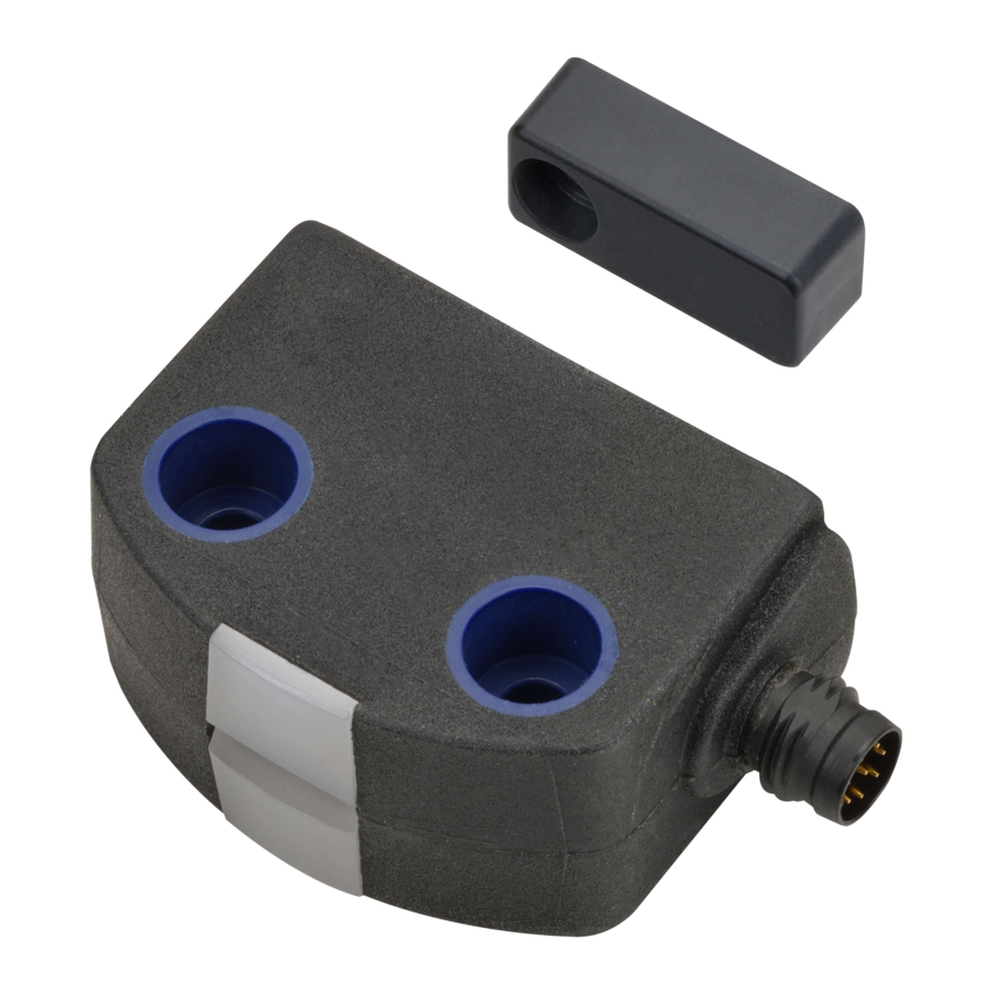
Model D41D
High-Coded Safety Door Switch
Instruction Manual
EN
Thank you for purchasing Omron products. This
product is a high-coded safety door switch.
Please read and understand this document
before using the products. Keep this document
ready to use whenever needed. Only qualified
person
trained
in
professional
electrical
technique should handle the product. Please
consult your Omron representative if you have
any questions or comments. Make sure that
information written in this document are
delivered to the final user of the product.
© OMRON Corporation 2021 All Rights Reserved.
Original Instructions
5673883-0A
The D41D High-Coded Safety Door Switch is designed for
safety circuits and is used to monitor the position of movable
guards.
EU Declaration of Conformity
OMRON declares that the D41D is in conformity with the
requirements of the following EU Directives:
Machinery Directive 2006/42/EC
RE Directive 2014/53/EU
Standards
D41D is designed and manufactured in accordance with the
following standards:
• EN ISO 13849-1: 2015 PL e Category 4
• EN 60947-5-3
• EN 300 330
• EN ISO 14119
• IEC 61508
• EN 62061
Dispose in accordance with applicable regulations.
Safety Precautions
Indicates a potentially
hazardous situation which, if
not avoided, will result in
minor or moderate injury, or
WARNING
may result in serious injury or
death. Additionally there may
be significant property
damage.
Alert Statements
WARNING
Use only appropriate components or devices
complying with relevant safety standards
corresponding to the required performance
level and safety category. Failure to do so may
result in serious injury or death. Conformity to
requirements of the performance level and
safety category must be determined as an
entire system. It is recommended to consult a
certification body regarding assessment of
conformity to the required safety level.
Do not apply DC voltages exceeding the rated
voltages, nor any AC voltages to the product.
Failure to do so may result in serious injury or
death.
Install the switch and actuator in a position
where the opening of the guard door can be
detected within a safe distance. Failure to do so
may result in serious injury or death.
When complying with safety standards, install
the product in an appropriate manner in
accordance
with
ISO
14119,
with
consideration of the risk of defeat by the
operator. Failure to do so may result in serious
injury or death.
Make sure that the DC power supply meets the
following items. Failure to do so may result in
serious injury or death.
- Satisfies the requirements of PELV power
supply defined in IEC 60204-1.
- Satisfies the requirements of class 2 circuits
defined in UL508.
Precautions for Safe Use
(1) Disconnect the product from power supply
when wiring the product. Failure to do so may
cause unexpected operation of devices
connected to the product.
(2) Wire the input and output terminals correctly
and verify the correct operation of the product
before using the system in which the product
is incorporated. Incorrect wiring may lead to
loss of the safety function.
(3) Do not use the product in any direction other
than the specified mounting orientations of
the main body and actuator.
(4) Dispose of the product in accordance with the
laws set by each country.
Precautions for Correct Use
(1) Do not drop the product to the ground or expose to excessive
vibration or mechanical shocks. Doing so may damage the
product and cause failure.
(2) Do not store or use the product under the following conditions.
Doing so may damage the product and cause failure.
1) At ambient operating temperatures out of the range of -25 to 65°C
2) At ambient storage temperatures out of the range of -25 to 85°C
3) At relative humidity of 93% or more
4) In direct sunlight
5) Under drastic temperature changes
6) In high humidity that causes condensation
(3) Keep the product away from oil or solvent. Oil or solvent make
the marking on the product illegible and cause deterioration of
some parts.
(4) Do not use in an environment with corrosive gas.
(5) The product may not operate normally in the vicinity of devices
that generate strong radio waves or magnetic fields, such as
RFID systems, proximity sensors, motors, inverters, and
switch-mode power supplies. If the device is used in the
vicinity of such devices, check the effect before use.
(6) Installing the switch and the actuator on a metallic material
may affect the operating distance. If installation on a metallic
material is necessary, be sure to check the effect on the
operating distance before use.
(7) Tighten the screws with a specified torque.
(8) Use the wires specified by OMRON to wire the product.
(Refer to Connection.)
(9) Do not extend the cables in excess of the specification of this
product. Carry out electrical connection according to the wiring
examples shown in this document and verify the correct
operation of the product.
(10) During installation, make sure that the safety door switch does
not come in contact with the actuator due to rattling of the
guard door. (The performance of the product may be degraded
by a collision caused by opening or closing the guard door.)
(11) Do not pull or bend the cable excessively. A disconnection
may cause a malfunction.
(12) Risk time remains unchanged by series connection. However,
carry out electrical connection according to the wiring
examples shown in this document.
(13) Be sure to inspect the product daily and every 6 months.
Failure to do so may cause a system failure and serious injury.
(14) When determining the safety distance, take into account the
delay of the output of the product caused by the response time.
Failure to do so may cause the operator to reach the hazardous
source before the machine is stopped, resulting in serious injury.
(15) Install the product so that the LED indicators of the safety
door switch are as visible as possible. Misinterpreting the
status of the safety door switch may result in danger.
(16) Do not use the product at an altitude of 2,000 m or higher.
(17) Do not connect a product different from this product in series
with this product. Doing so may disturb waveforms of the
input and output signals, leading to loss of the safety function.
(18) Do not use the product in the water or continuous water
exposure environment. Doing so may cause water to leak into
the product. (The degree of protection does not guarantee the
protection under continuous water exposure environment.)
(19) Do not tamper the product with a replacement actuator. Store
replacement actuators in a safe place where they cannot be
easily reached.
(20) Build a safety system using the outputs of both Safety
Outputs 1 and 2. Wiring with only one safety output may lead
to loss of the safety function due to a single failure.
(21) Wiring should meet the requirements specified in Section
9.4.3 of IEC 60204-1 to prevent malfunction due to ground
faults in the safety output lines.
(22) Do not wire the product to an input of a safety controller in parallel.
(23) Do not try to disassemble, repair, or modify the product.
Doing so may cause loss of the safety function.
(24) Do not operate the product in an environment with flammable
or explosive gas.
(25) After installation of the product, qualified personnel should verify
to see that the installation, inspection, and maintenance are
properly performed. The qualified personnel should be qualified
and authorized to secure the safety on each phase of design,
installation, running, maintenance and disposal of system.
(26) Auxiliary output is NOT a safety output. Do not use the
Auxiliary output individually for any safety function. Such
incorrect use causes loss of the safety function of the product
and its relevant systems.
(27) Disconnect the product and the controller connected to the
product from power supply when replacing the product.
Failure to do so may cause unexpected operation of devices
connected to the product.
(28) The safety function may not operate normally due to a
malfunction of the wiring, setting, or switch, and the machine may
continue to operate, which may result in personal injury. Make
sure that the safety function works before starting operation.
(29) Do not use the product as a door stopper. (The performance
of the product may be degraded due to a collision caused by
opening and closing the guard door.)
Detection Range (Typical Data)
Operating distance
The side allows for a maximum height misalignment (X) of safety
door switch and actuator of ±8 mm (e.g. mounting tolerance or due
to guard door sagging). The axial misalignment (Y) is max. ±18 mm.
Actuating curves
The actuating curves represent the typical operating distance of
the safety door switch during the approach of the actuator subject
to the actuating direction.
Transverse misalignment
S [mm]
12
10
5
0
-20
-15
-10
-5
0
5
10
15
20
Y [mm]
Height misalignment
S [mm]
12
due
10
5
0
-24
-20
-15
-10
-5
0
5 10
15
20 24
X [mm]
The continuous signal of the yellow LED signals the actuator
detection; the flashing of the yellow LED signals that the safety door
switch is actuated in the different travel area.
Preferred actuation directions: from front or from side
In case of a lateral actuation, the operating distances are reduced
by approx. 3 mm.
Recommended Adjustment
Align the safety door switch and actuator at a distance of 0.5 x
assured operating distance (Sao).
The correct functionality of both safety channels must be checked
by means of the connected safety controller.
Actuator Mounting Direction
Actuation from front
Actuation from side
Note: 1. Lateral actuation only from the shown side of the safety door switch.
Ratings and Specifications
Model
Technical
Detection method
Frequency band
Transmitter outputs
Interlock type (ISO 14119)
Coded level (ISO 14119)
Actuator
Response time (ON to OFF)
Risk time
Startup time
Typical operating distance
(Sn)(IEC 60947-5-3)
Assured operating distance
(Sao)
(IEC 60947-5-3)
Assured switch-off distance
(Sar)
Differential travel
Repeat accuracy (R)
Electrical
Supply voltage (Ue)
Current consumption (Io)
Overvoltage category
Pollution degree
Conditional short-circuit current
External device fuse rating
Safety input
Accepted test
pulse duration
on input signal
Test pulse interval
Current
consumption
per input
Safety output Switching element PNP type, short-circuit proof
(OSSD)
Utilization category
Operating current
(Ie1)
Voltage drop (Ud) <1 V
Test pulse duration 1.0 ms max.
Test pulse interval 1,000 ms
Auxiliary
Switching element PNP type, short-circuit proof
output
Utilization
category
Operating
current (Ie2)
Voltage drop (Ud) <2 V
Switching frequency (f)
Rated insulation voltage (Ui)
Rated impulse withstand
voltage (Uimp)
Minimum operating current (Im)
OFF-state leakage current (Ir)
Mechanical
Fixing screws
Tightening torque of fixing
screws
Material
Weight
Environmental
Ambient operating temperature
Ambient storage temperature
(including during transportation)
Ambient operating humidity
Degree of protection
(IEC 60529)
Vibration resistance
Shock resistance
Connection
Series connection
Cable lengths
Connection
*1. Refer to the product catalog for connection specifications with the
controller.
Safety classification information
Standard
ISO 13849-1, IEC 61508, IEC 62061
PL
e
DC
99 %
Safety category
4
PFH (number)
6.8 x10
PFD
1.2 x 10
SIL
Suitable for SIL3 applications
Y
20 years
Mission time
Note:1. If multiple safety door switches are involved in the same
safety function, the PFH values of the individual
components must be added.
For use in NFPA 79 Applications.
Adapters providing field wiring means are available from the
manufacturer. Refer to manufacturer's information.
For use in Pollution Degree 2 Environment.
This device complies with part 15 of the FCC Rules and Industry
Canada license-exempt RSS standard(s).
Operation is subject to the following two conditions:
(1) This device may not cause harmful interference, and
(2) this device must accept any interference received, including
interference that may cause undesired operation.
This device complies with the Nerve Stimulation Exposure Limits
(ISED RSS-102) for direct touch operations. Changes or
modifications not expressly approved by OMRON Corporation
could void the user's authority to operate the equipment.
Le présent appareil est conforme aux CNR d'Industrie
Canada applicables aux appareils radio exempts de licence.
L'exploitation est autorisée aux deux conditions suivantes:
(1) l'appareil ne doit pas produire de brouillage, et
(2) l'utilisateur de l'appareil doit accepter tout brouillage
radioélectrique subi, même si le brouillage est susceptible d'en
compromettre le fonctionnement.
[Unit: mm]
Cet appareil est conforme aux limites d'exposition relatives à la
stimulation des nerfs (ISED CNR-102) pour les operations
tactiles directes. Changements ou modifications non
expressément approuvés par OMRON corporation pourrait
12
annuler le droit de l'utilisateur à utiliser l'équipement.
12
2
9
2
9
D41D
active area
RFID
Safety door switch
125 kHz
D41D-*CD-N1
-6 dBm max.
Type 4
D41D-1: High (individual coding)
D41D-2: High (individual coding re-teaching enabled)
D41D-A1, D41D-A2, D41D-A3
100 ms max.
200 ms max.
2 s max.
12 mm
(lateral actuation: 9mm)
10 mm (-10 to 60°C)
6 mm (-10 to 60°C, lateral)
D41D-*CD-025N2
8 mm (-25 to 65°C)
4 mm (-25 to 65°C, lateral)
47
18 mm
(lateral actuation: 15 mm)
<2.0 mm
<0.5 mm
24 VDC (-15%/+10%)
(stabilized PELV-power supply)
35 mA
Actuator
III
3
D41D-A1: M4 screw
(UL certification is 2)
(Tightening torque: 0.8 N•m)
100 A
2 A max.
1.0 ms max.
100 ms min.
5 mA
DC-12: 24 VDC (Ue)/0.25 A (Ie)
D41D-A2 : M5 screw
DC-13: 24 VDC (Ue)/0.25 A (Ie)
(Tightening torque: 2 N•m)
0.25 A max.
DC-12:24 VDC (Ue)/0.05 A (Ie)
DC-13:24 VDC (Ue)/0.05 A (Ie)
0.05 A max.
1 Hz
32 VDC
0.8 kV
0.5 mA
<0.5 mA
2×M4
(Refer to the outline drawing for the actuator)
0.8 N•m
The mounting holes provide for a mounting by means of M4 screws
(Refer to the outline drawing for the actuator)
(max. tightening torque 0.8 N•m). The product can be mounted in any
Thermoplastic PBT (enclosure)
position. The minimum bend radius of the -025-type cable is 25 mm.
Unit: <50 g, Packaged: <110 g
The active areas of the safety door switch and the actuator have to
face each other. The safety door switch must only be used within the
-25 to 65°C
assured operating distances ≤ Sao and ≥ Sar.
-25 to 85°C
To avoid any interference inherent to this kind of system and any
93% max.
(non-condensing, non-icing)
reduction of the operating distances, please observe the following
guidelines:
IP65 and IP67
10 to 55 Hz, amplitude 1.0 mm
• See the figures below for the minimum distances between two safety
30 g/11 ms
door switches and other systems of the same frequency (125 kHz).
31 max. (*1)
100m max.
(between switch and power supply)
D41D-1CD-N1: Connector plug M8,
8-pole, A-coded
D41D-2CD-025-N2: Connecting cable
0.25-m long with connector M12
/h
-10
-4
Sealing Kit (D41D-SK)
Contents: 4 flat plugs and 4 plugs with rim for high screw head
Purpose: Used to seal the mounting holes
Mounting Kit (D41D-MS)
Contents: 2 mounting plates and 4 ferrule plugs
Purpose (Mounting plate): Used to fix to a non-flat surface such as a
profile.
Purpose (Ferrule plug): Used for applications with considerable
changes in ambient temperature.
Dimensions
[Unit: mm]
M4
18
22
39.2
LED indications
47.5
25
43
250
±10
22
M4
18
39
D41D-A3 : M3 screw
(Tightening torque: 0.6 N•m)
22
60
15
M3
M5
6 dia.
40
1.2 dia.
4
16.5
Mounting
[Unit: mm]
50
109
90
100
Accessory
[Unit: mm]
Advertisement

Related Manuals for Omron D41D


Summary of Contents for Omron D41D
- Page 1 (7) Tighten the screws with a specified torque. 200 ms max. Risk time product is a high-coded safety door switch. (8) Use the wires specified by OMRON to wire the product. Startup time 2 s max. Please read and understand this document Typical operating distance 39.2...
- Page 2 Ambient temperature too high without function pulses 5 flash Incorrect or defective actuator Note: 1. When using an OMRON cable, the tightening torque of the connector is 1 N • m pulses Continuous Internal fault, Wiring Examples with yellow flashing teaching procedure The application examples shown are suggestions.