Table of Contents
Advertisement
Quick Links
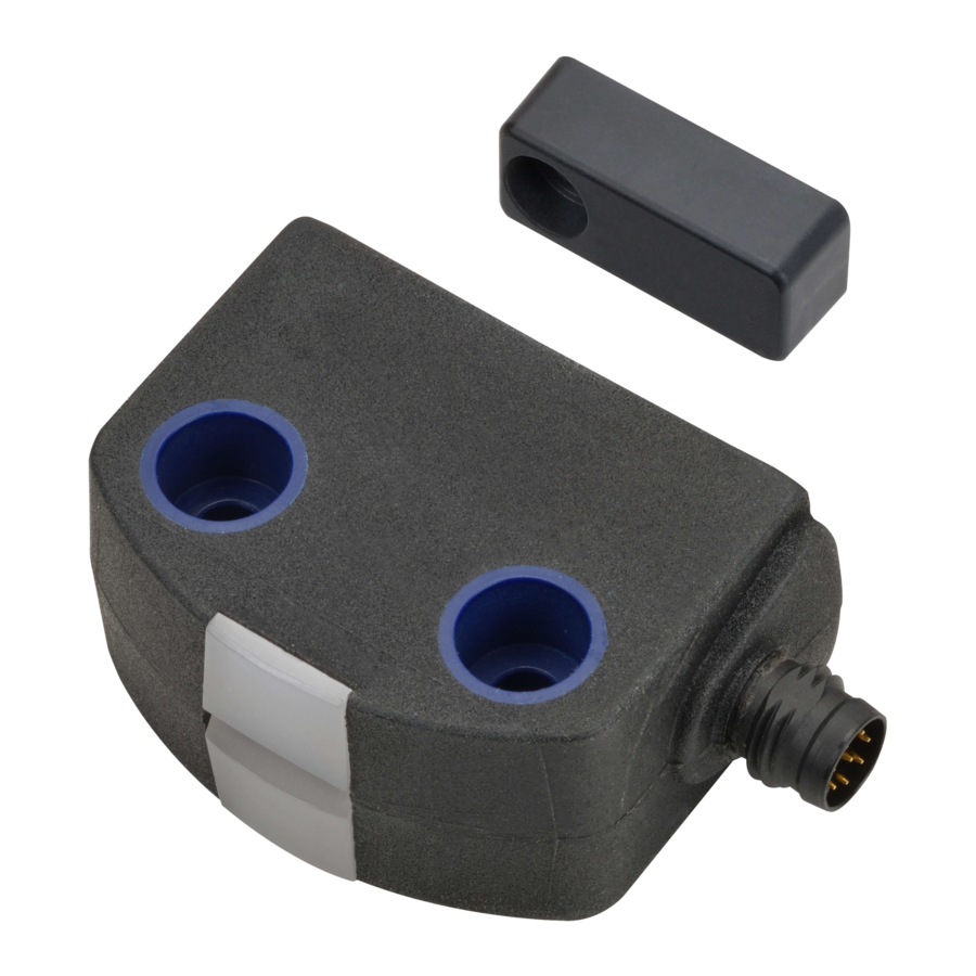
High-Coded Non-Contact Safety Door Switch
D41D
Matches with machine design.
Initial setup by batch pairing is
quick and easy.
• Tamper-proof safety door switch to prevent human error
• Easy automatic pairing
• Fits in narrow spaces and corners inside machines
• Three types of actuators
• Complies with ISO 14119 (Type 4/High Coded),
ISO 13849-1 (PLe)
Refer to Safety Precautions on page 17
Three types of actuators fit in narrow spaces and corners inside machines
D41D-A1
Installation example: swinging door
• Fits in narrow spaces and corners
A high-coded safety switch is defined as one where a sensor is paired with a high level coded actuator for which more than 1,000
variations are available.
D41D-A2
Installation example: acrylic glass door
• Flat design matches the surroundings
* The actuator is sold separately.
For the most recent information on models that have been certified for
safety standards, refer to your OMRON website.
D41D-A3
Installation example: sliding door, narrow space
• Compact size for acrylic glass doors
1
Advertisement
Table of Contents

Related Manuals for Omron D41D


Summary of Contents for Omron D41D
- Page 1 * The actuator is sold separately. For the most recent information on models that have been certified for safety standards, refer to your OMRON website. Refer to Safety Precautions on page 17 Three types of actuators fit in narrow spaces and corners inside machines...
-
Page 2: High (Individual Coding)
D41D Model Number Structure Model Number Legend Safety Door Switch Sensor D41D - @ C D - @ @ (2) (3) (5) (6) (1) Model D: Non-Contact (2) Coding level / Teaching limitation 1: High (Individual coding) 2: High (Individual coding, No limitation) -
Page 3: Table Of Contents
D41D Ordering Information List of Models Sensors Appearance Coding level / Teaching limitation Connection Cable length Model High Connector (M8) D41D-1CD-N1 (Individual coding) High Connecting cable 0.25-m long with D41D-2CD-025N2 (Individual coding/No limitation) Connector (M12) Actuator (Sold separately) Appearance Name... - Page 4 • UL508 • CAN/CSA C22.2 No.14 Regions where D41D can be used The product can be used in Japan, the United States of America, Canada, EU member states, the United Kingdom, and People's Republic of China. The use in other countries may conflict with radio laws of the countries.
- Page 5 Transmitter outputs -6 dBm max. Interlock type (ISO 14119) Type 4 D41D-1: High (individual coding) Coded level (ISO 14119) D41D-2: High (individual coding, No limitation) Actuator D41D-A1, D41D-A2, D41D-A3 Response time (ON to OFF) 100 ms max. Risk time 200 ms max.
-
Page 6: D41D-1Cd-N1
2. this device must accept any interference received, including interference that may cause undesired operation. This device complies with the Nerve Stimulation Exposure Limits (ISED RSS-102) for direct touch operations. Changes or modifications not expressly approved by OMRON Corporation could void the user‘s authority to operate the equipment. - Page 7 D41D Engineering Data (Typical Data) Detection Range Operating distance The side allows for a maximum height misalignment (X) of sensor and actuator of ±8 mm (e.g. mounting tolerance or due to guard door sagging). The axial misalignment (Y) is max. ±18 mm.
-
Page 8: D41D-A1
D41D Actuator Mounting Direction (Unit: mm) D41D-A1 Actuation from front Actuation from side Lateral actuation only from the shown sensor side. D41D-A2 Actuation from side Actuation from front Lateral actuation only from the shown sensor side. D41D-A3 Actuation from side Actuation from front Lateral actuation only from the shown sensor side. - Page 9 BLUE without function Note: 1. When using an OMRON cable, the tightening torque of the connector is 1 N•m Wiring Examples The application examples shown are suggestions. They however do not exempt the user from carefully checking whether the Safety door switch and its set-up are suitable for the individual application.
- Page 10 OMRON’s safety relay unit Input device Connectable *1 D41D Connectable Not connectable Connectable Safety-door switch *1. The G9SX-NS@ cannot be connected to D41D. *2. Refer to the instruction manual or user’s manual of each product for how to extend the wiring.
- Page 11 When the above procedure is attempted with a D41D-1 which already completed teaching, the teaching procedure will not start. For ordering suffix D41D-2, the teach-in procedure for a new actuator can be repeated an unlimited number of times. When a new actuator is taught, the code, which was applicable until that moment, becomes invalid.
- Page 12 D41D Operating Principle Operating Principle Diagnostic Functions Operating principle of the diagnostic LEDs The safety outputs can be connected to the safety circuit of the control system. The opening of a guard door, i.e. the actuator is removed out The safety door switch indicates the operating condition and faults by...
- Page 13 D41D Dimensions (Unit: mm) Sensors D41D-1CD-N1 39.2 active area 47.5 D41D-2CD-025N2 ±10 active area...
- Page 14 The actuator can be prevented from twisting caused by screw tightening torque during installation by passing a pin up to 1.1 16.5 mm in size through the hole in the rear section of the D41D-A3. M3 screw active area (Tightening torque: 0.6 N•m) 1.2 dia.
- Page 15 D41D Mounting The mounting holes provide for a mounting by means of M4 screws (max. tightening torque 0.8 N•m). The product can be mounted in any position. The minimum bend radius of the -025-type cable is 25 mm. The active areas of the safety door switch and the actuator have to face each other.
- Page 16 D41D Troubleshooting Error Errors that, which no longer guarantee the function of the safety door switch (internal errors) cause the safety outputs to be disabled within the risk time. After the rectification of the error, the error message is reset by opening the corresponding guard door.
- Page 17 D41D Safety Precautions Be sure to read the precautions for all models in the website at: http://www.ia.omron.com/. Indication and Meaning for Safe Use Precautions for Safe Use Warning Indications 1. Disconnect the product from power supply when wiring the product. Failure to do so may cause unexpected operation of Indicates a potentially hazardous devices connected to the product.
- Page 18 D41D 19.Do not tamper the product with a replacement actuator. Store replacement actuators in a safe place where they cannot be easily reached. 20.Build a safety system using the outputs of both Safety Outputs 1 and 2. Wiring with only one safety output may lead to loss of the safety function due to a single failure.
- Page 19 D41D Set-up and Maintenance/Disassembly and Disposal Set-up and Maintenance Disassembly and Disposal Disassembly Functional testing The product must be disassembled in a de-energized condition only. The safety function of the safety components must be tested. The following conditions must be previously checked and met: Disposal 1.
- Page 20 MEMO...
- Page 21 Return of any Products by Buyer must be approved in writing by Omron before shipment. Omron Companies shall not be liable for the suitability or unsuitability or the results from the use of Products in combination with any electrical or electronic components, circuits, system assemblies or any other materials or substances or environments.
- Page 22 * The actuator is sold separately. The actuator is sold separately. For the most recent information on models that have been certified for safety standards, refer to your OMRON website. Refer to Safety Precautions on page 17 Refer to Safety Precautions on page18 For the most recent information on models that have been certified for safety standards, refer to your OMRON website.