Table of Contents
Advertisement
Available languages
Available languages
Quick Links
Advertisement
Table of Contents

Related Manuals for Neatech JOB


Summary of Contents for Neatech JOB
- Page 1 User and maintenance manual...
- Page 3 European Directive 93/42; 93/42; secondo i criteri di classificazione according criteria dell’allegato IX della suddetta classification of annex IX of this direttiva, la Job è classificata come Directive, the Job is classified as dispositivo medico di classe I class I medical device...
- Page 4 SMALTIMENTO Questo prodotto ed ogni suo componente non può essere smaltito come rifiuto domestico. Per informazioni più dettagliate sulla modalità di riciclaggio e smaltimento di questo prodotto rivolgersi al servizio locale di smaltimento rifiuti. DISPOSING This product and all its components can not be treated as household waste.
-
Page 5: Table Of Contents
Revisione manuale 2017-08 Revision date Manuale utente italiano Presentazione della carrozzina ............ 7 Messa in funzione ............... 8 Controlli da compiere all’atto della consegna ....8 2.1. 2.2. Unpacking ................8 2.3. Operazioni di montaggio ............ 9 2.4. Trasporto e immagazzinamento ........13 Regolazioni ................ - Page 6 5.5. Istruzione per la sostituzione delle parti ......27 5.5.1. Assieme ruota ............28 5.5.2. Telino seduta............. 29 5.5.3. Telo poggiapiedi ............30 5.5.4. Telo schienale ............30 5.5.5. Kit clips di bloccaggio ..........31 5.5.6. Barra antiribaltamento ..........32 5.5.7.
- Page 7 Maintenance ................57 5.1. Maintenance and cleaning ..........57 5.2. Controls to be performed on the wheelchair..... 57 5.3. Tire puncture ..............58 5.4. Specifications ..............59 5.4.1. Dimensions ............... 60 5.5. Instructions for parts replacement ........61 5.5.1. Wheel assembly ............62 5.5.2.
-
Page 9: Presentazione Della Carrozzina
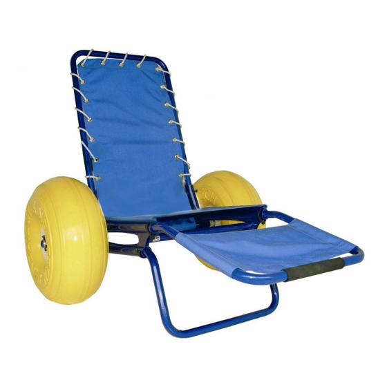
Ti ringraziamo per aver scelto un nostro prodotto. La JOB è una sedia per il trasporto di disabili ed anziani adatta al mare, alla neve o al trekking off-road. È munita, infatti, di una coppia di ruote studiate per il trasporto agevole su tutti i tipi di fondo (sabbia, ciottoli, neve). -
Page 10: Messa In Funzione
Telaio principale completo di telo seduta e bloccaggi per tubo • N. 2 Ruote pneumatiche • N. 10 Clips di bloccaggio • Documentazione • Eventuali accessori acquistati SMALTIMENTO IMBALLAGGIO Per riciclare correttamente i materiali di imballaggio della Job seguire le indicazioni fornite dal servizio locale di smaltimento rifiuti www.neatech.it... -
Page 11: Operazioni Di Montaggio
Assicurarsi che i tubi risultino correttamente agganciati. Figura 1 ATTENZIONE I tubi (D) e (C) hanno uguale diametro ma (D) è più lungo. Se si invertono i tubi (D) e (C), la carrozzina risulta sbilanciata con possibili pericoli per l’occupante. www.neatech.it... - Page 12 Assicurarsi che le clips siano ben agganciati sui mozzi delle ruote. Figura 2 Schienale Inserire lo schienale nei tubi di supporto del telaio principale come mostrato in Figura 3, quindi inserire negli appositi fori le due clips di bloccaggio per fissarlo. Assicurarsi che i bloccaggi siano ben agganciati. www.neatech.it...
- Page 13 Quindi fissare la fascia posta alla fine dello schienale passandola intorno all’asse delle ruote così come mostrato in Figura 4. Figura 4 ATTENZIONE È necessario fissare accuratamente lo schienale con le clips di fissaggio e stringere bene il velcro per evitare un suo accidentale smontaggio. www.neatech.it...
- Page 14 ATTENZIONE Assicurarsi che i tubi risultino correttamente agganciati. Smontaggio della carrozzina Per smontare la carrozzina eseguire all’inverso le operazioni descritte. Assicurarsi che i bloccaggi di ruote e tubi rimangano incastrati nei rispettivi alloggiamenti del telaio per evitarne la perdita. www.neatech.it...
-
Page 15: Trasporto E Immagazzinamento
Se non si intende usare la carrozzina per un lungo periodo, conservarla in un luogo pulito. Se è necessario trasportare la carrozzina Job, per facilitare le operazioni, è possibile smontarla come descritto nel paragrafo 2.3 e riporla nell’apposita borsa fornita come accessorio. -
Page 16: Regolazioni
3. Regolazioni 3.1. Regolazione poggiagambe Per la regolazione del poggiagambe sganciare le due clips di bloccaggio come mostrato in Figura 7. Mettere il poggiagambe in una delle tre posizioni disponibili e inserire nuovamente le due clips di bloccaggio. Figura 7 www.neatech.it... -
Page 17: Uso Della Carrozzina
Per un uso in sicurezza dell’ausilio e per evitare situazioni di rischio per l’utente verificare che la circonferenza delle ruote sia compresa tra 1380 e 1400 mm. In caso contrario gonfiare o sgonfiare la ruota fino a rientrare nel range desiderato. Figura 8 www.neatech.it... -
Page 18: Accessori
4.1. Accessori La Job può essere equipaggiata con molteplici accessori che il produttore mette a disposizione per soddisfare le diverse esigenze del cliente. 4.1.1. Coppia di braccioli Montare i braccioli (dx e sx) allo schienale come mostrato in Figura 9. Per assicurarsi un sicuro collegamento, avvitare correttamente le due viti in Figura 9 utilizzando un chiavino per bulloni ad esagono incassato da 6 mm. -
Page 19: Kit Terza Ruota
Figura 11. Applicare dunque le clips di bloccaggio negli appositi fori per assicurare il corretto collegamento. L’eventuale regolazione in profondità è uguale alla regolazione fatta per la struttura poggiagambe. Per maggiori informazioni vedere paragrafo 3.1. www.neatech.it... - Page 20 Prima di utilizzare il kit terza ruota controllare la pressione del pneumatico. La circonferenza della terza ruota deve essere compresa fra 81 cm e 84 cm. In caso contrario gonfiare o sgonfiare la ruota fino a che la sua circonferenza rientra nel range indicato. www.neatech.it...
-
Page 21: Tendalino Parasole
Borsello contenente il tendalino e le cinghie di aggancio (1) • Supporti per il tendalino (2) • Barre di sostegno del tendalino (3) Figura 12 Dalle barre di supporto del tendalino rimuovere il copritubo nero individuando il foro che non presenta linguette esterne (vedi Figura 13). Figura 13 www.neatech.it... - Page 22 Mantenere i supporti a testa piatta in posizione parallela al terreno e rivolti verso l’alto. Figura 14 Facendo riferimento alla Figura 15 agganciare la cinghia al tubolare sul retro dello schienale in modo che il moschettone sia rivolto verso l’esterno. Figura 15 www.neatech.it...
- Page 23 Agganciare la cinghia posta sul retro tendalino moschettone della cinghia precedentemente fissata tubolare e tirare le cinghie fino a che siano tese. Figura 16 Agganciare i tiranti del tendalino ai tubolari del poggiagambe. Figura 17 www.neatech.it...
- Page 24 Regolare la tensione dei tiranti agendo sui fermi a pressione fino a che il tendalino è stabile rispetto alla sedia. Figura 18 www.neatech.it...
-
Page 25: Manutenzione
5.1. Manutenzione e pulizia Una manutenzione regolare contribuisce a conservare intatte le funzionalità e la sicurezza della Job. La carenza o l’insufficienza di cure e di manutenzione comporta una limitazione della garanzia da parte del produttore. Per la pulizia della sedia non utilizzare dispositivi a spruzzo d’acqua ad alta pressione. -
Page 26: Foratura Pneumatici
Pulire la zona danneggiata con alcool etilico. • Quando la superficie è asciutta, applicare alcune gocce di sigillante per PVC morbido. • attendere alcuni minuti affinché la colla si secchi, quindi gonfiare la ruota come descritto in questo manuale. www.neatech.it... -
Page 27: Specifiche Tecniche
5.4. Specifiche tecniche 125 kg Massimo peso utente 7 Kg - Telaio Peso a vuoto 3 Kg – Ruota La Job è destinata a tutte quelle categorie di Utilizzo previsto utenti con difficoltà motorie temporanee o permanenti hanno l’esigenza compiere spostamenti sulla spiaggia e su altri tipi di superfici impervie. -
Page 28: Dimensioni
5.4.1. Dimensioni 1250 Le caratteristiche possono variare in base alla specifica personalizzazione di ogni singola carrozzina. www.neatech.it... -
Page 29: Istruzione Per La Sostituzione Delle Parti
R105-002 Telo poggiapiedi R105-003 Telo schienale R105-004 Kit clips di bloccaggio R105-005 Barra antiribaltamento R105-006 Struttura poggiagambe R105-007 Supporto anteriore R105-008 Tappo per estruso bracciolo R105-009 Tubo schienale completo di telo R105-010 Assieme ruotino R105-011 Tondino tubo seduto R105-012 www.neatech.it... -
Page 30: Assieme Ruota
(F). Assicurarsi che la clip sia ben agganciata sul mozzo delle ruote. Figura 19 Codice Descrizione R105-001 Assieme ruota www.neatech.it... -
Page 31: Telino Seduta
Per la rimozione del telo seduta, sfilarlo semplicemente come evidenziato in Figura 20. Inserire il nuovo telo negli appositi tubolari. Figura 20 Laddove necessario è possibile sostituire anche il solo tondino tubo seduta sfilandolo semplicemente dal telino. Codice Descrizione R105-002 Telino seduta R105-012 Tondino tubo seduta www.neatech.it... -
Page 32: Telo Poggiapiedi
Successivamente sfilare la corda, e infine togliere la fascetta che la mantiene collegata ai tubolari. Inserire il nuovo telo seguendo le indicazioni in verso contrario. Codice Descrizione R105-004 Telo schienale www.neatech.it... -
Page 33: Kit Clips Di Bloccaggio
Figura 21 Le clips di serraggio come evidenziato in Figura 21 si trovano nelle posizioni di seguito elencate: N°2 Tubolare schienale N°1 Ruota Job destra N°1 Ruota Job sinistra N°2 Supporto poggiagambe N°2 Supporto anteriore N°2... -
Page 34: Barra Antiribaltamento
Per la sostituzione della barra antiribaltamento, togliere le due clips di bloccaggio e sfilare la barra come mostrato in Figura 22. Inserire la nuova barra nella stessa posizione e assicurarsi di inserire correttamente le clips di bloccaggio. Figura 22 Codice Descrizione R105-006 Barra antiribaltamento www.neatech.it... -
Page 35: Struttura Poggiagambe
Per la sostituzione della struttura poggiagambe, togliere le due clips di bloccaggio e sfilare la barra come mostrato in Figura 23. Inserire la nuova barra nella stessa posizione e assicurarsi di inserire correttamente le clips di bloccaggio. Figura 23 Codice Descrizione R105-007 Struttura poggiagambe www.neatech.it... -
Page 36: Supporto Anteriore
Per la sostituzione del tappo per estruso bracciolo (dx o sx), togliere il vecchio tappo come evidenziato in Figura 25. Inserire il nuovo nella stessa posizione applicando una leggera forza. Figura 25 Codice Descrizione R105-009 Tappo per estruso bracciolo www.neatech.it... -
Page 37: Tubo Schienale Completo Di Telo
Per la sostituzione del tubo schienale completo di telo, togliere le due clips di bloccaggio e sfilare la barra come mostrato in Figura 26. Inserire il nuovo schienale nella stessa posizione e assicurarsi di inserire correttamente le clips di bloccaggio. Figura 26 Codice Descrizione R105-010 Tubo schienale completo di telo www.neatech.it... -
Page 38: Assieme Ruotino
Figura 27 utilizzando un chiavino per bulloni ad esagono incassato da 5 mm, allargare i due tubolari e sfilare la ruota. Inserire la nuova ruota, agganciare i due tubolari e assicurarsi di stringere correttamente le viti tolte in precedenza. Figura 27 Codice Descrizione R105-011 Assieme ruotino www.neatech.it... -
Page 39: Condizioni Di Garanzia
6. Condizioni di garanzia La JOB è un prodotto globalmente garantito per 24 mesi. La garanzia è valida per difetti di materiale o di lavorazione. Sono escluse dalla garanzia le parti soggette ad usura e le parti danneggiate da: eccessivo carico, utilizzo non corretto, modifiche e riparazioni apportate da terzi non autorizzati dalla Neatech.it s.r.l. - Page 41 ENGLISH MANUAL...
-
Page 43: Product Presentation
Dear Friend, Thank You for choosing our product. The JOB is a chair for the transport of elderly and disabled people adapted to the sea, snow or off-road trekking. It is provided with a pair of wheels designed for an easy transport on all type of surface (sand, pebbles, snow). -
Page 44: Starting Up
Main frame with upholstery and tube fasteners • N. 2 Pneumatic wheels • N.2 wheel fasteners • Documentation • Purchased accessories PACKAGING DIASPOSAL To properly recycle the packaging materials follow the instructions provided by your local waste disposal service. www.neatech.it... -
Page 45: Mounting The Wheelchair
Make sure tubes are correctly locked. Figure 29 WARNING Tubes (D) and (C) are of the same width but (D) is longer. If tubes (D) and (C) are inverted, the wheelchair will result unbalanced with possible risk for the user. www.neatech.it... - Page 46 Figure 30 Backrest Insert the backrest into the bushings on the main frame as shown in Figure 31, then insert the 2 fasteners deeply through proper holes to lock it. Make sure fasteners are correctly locked on main frame. www.neatech.it...
- Page 47 After that fix strip located on bottom end of the backrest, passing it around wheels’ axle as shown in Figure 32. Figure 32 WARNING It is very important to carefully fix the backrest with the fixing clips and the strip to avoid possible dismounting www.neatech.it...
- Page 48 Tighten correctly the two tubes. Disassembly of the wheelchair In order to disassemble the chair run the described operations in reverse. Make sure that the looking of the wheels and tubes are trapped in their respective housings of the frame to prevent loss. www.neatech.it...
-
Page 49: Transport And Storage
2.4. Transport and storage If you don’t want to use the Job for a long time, store it in a safe place free from dust and moisture. If you want to carry the wheelchair, in order to facilitate operations, it is possible to disassemble it as described in section 2.3 and put it in the bag available as... -
Page 50: Adjustments
3. Adjustments 3.1. Legrest adjustment To adjust the position of legrest, remove the fasteners as shown in Figure 35. Put the legrest in one of the three available positions and insert again the fasteners. Figure 35 www.neatech.it... -
Page 51: Use Of The Wheelchair
For use in safety of the wheelchair and to avoid situations of risk for the user, verify that the circumference of the wheels is between 1380 and 1400 mm . If not inflate or deflate the wheel to within the recommended range. Figure 36 www.neatech.it... -
Page 52: Accessories
4.1. Accessories The Job can be equipped with many accessories that Neatech.it makes available to meet different customer needs. 4.1.1. Armrests Assemble the armrest (rh and lh) to the backrest as shown in Figure 37. To ensure a proper connection tighten the two screws shown in Figure 37 with a 6 mm allen... -
Page 53: Third Wheel Kit
So connect the third wheel kit inserting the tubes into the holes in front of the frame as shown in Figure 39. Then apply the fasteners into the appropriate holes to ensure proper connection. The depth adjustment is the same adjustment as for the legbar. For more information see section 3.1. www.neatech.it... - Page 54 Before using the third wheel kit, control that the pressure of the tire is correct. Make sure that the circumference of the wheel is between 81 cm and 84 cm . If not inflate or deflate the wheel until its circumference is in the recommended range. www.neatech.it...
-
Page 55: Sun Awning
Bag with awning and the straps for the coupling (1) • Supports for the awing (2) • Awning’s support bars (3) Figure 40 From the support bars of the awnings remove the pipe cover black identifying the hole that has no outer tabs (see Figure 41). Figure 41 www.neatech.it... - Page 56 Keep the media flat-head upright and facing up. Figure 42 Seeing Figure 43 attach the strap to the tubular on the back of the backrest so that the hook is facing towards the outside. Figure 43 www.neatech.it...
- Page 57 Attach the strap on the back of the awning to the hook of the belt previously fixed to the tube and pull the belts till they are very stretched. Figure 44 Attach the ties of the awning to the tubular of the legrest. Figure 45 www.neatech.it...
- Page 58 Adjust the tension of the tie rods acting on cord lock till the awning is stable with respect to the chair. Figure 46 www.neatech.it...
-
Page 59: Maintenance
Any work on the wheelchair must be performed by an authorized service center 5.1.Maintenance and cleaning Regular maintenance helps to keep intact the functionality and safety of JOB. Inadequate or lack of care and maintenance may cause a limitation of the warranty from the manufacturer. -
Page 60: Tire Puncture
In case of tire puncture please follow these instructions. • Clean damaged surface with ethylic alcohol. • When surface is dry; apply few drops of a glue for rigid PVC. • Wait some minutes to let glue dry, then inflate wheels as described in this manual. www.neatech.it... -
Page 61: Specifications
Maximum user weight 7 Kg – Chassis Empty weight 3 Kg – Wheel Job is intended to all those categories of Intended use users with temporary or permanent mobility difficulties who need to make trips to the beach and other types of impervious surfaces. -
Page 62: Dimensions
5.4.1. Dimensions 1250 Specifications may change according to the customization of each wheelchair. www.neatech.it... -
Page 63: Instructions For Parts Replacement
Sling legrest R105-003 Sling backrest R105-004 Fasteners kit R105-005 Anti-tips bar R105-006 Legbar structure R105-007 Front support R105-008 Cap for extruded armrest R105-009 Backrest tube including sling backrest R105-010 Third wheel assembly R105-011 Axis of the sling seat R105-012 www.neatech.it... -
Page 64: Wheel Assembly
(F). Make sure that the fastener is securely attached to the hub of the wheels. Figure 47 Code Description R105-001 Wheel assembly www.neatech.it... -
Page 65: Sling Seat
To remove the sling seat, simply pull out as shown in Figure 48. Enter the new seat in the appropriate tube. Figure 48 If necessary it is possible to replace only the rod axis simply by pulling it out of the sling seat. Code Description R105-002 Sling seat R105-012 Axis of the sling seat www.neatech.it... -
Page 66: Sling Legrest
After that remove the rope, and then remove the ties that keeps it attached to the tubes. As described enter the new sling backrest in the opposite direction. Code Description R105-004 Sling backrest www.neatech.it... -
Page 67: Fasteners Kit
Figure 49 The fasteners as shown in Figure 49 are located in the positions listed below: N°2 Backrest tube N°1 Right wheel N°1 Left wheel N°2 Legrest support N°2 Front support N°2 Anti-tips bar Code Description R105-005 Kit of fasteners www.neatech.it... -
Page 68: Anti-Tips Bar
To change the anti-tip bar, remove the two fasteners and pull the bar as shown in Figure 50. Insert the new bar in the same position, and be sure to properly insert the fasteners. Figure 50 Code Description R105-006 Antip-tips bar www.neatech.it... -
Page 69: Legrest Structure
To substitute the footrest structure remove the two fasteners and pull the bar as shown in Figure 51. Insert the new bar in the same position, and be sure to properly insert the fasteners. Figure 51 Code Description R105-007 Legrest structure www.neatech.it... -
Page 70: Front Support
To substitute the cap for extruded armrest (rh and lh), remove the old cap as shown in Figure 53. Insert the new one in the same position applying a light pressure. Figure 53 Code Description R105-009 Cap for extruded armrest www.neatech.it... -
Page 71: Backrest Tube Including Sling Backrest
To substitute the backrest tube comprehensive of sling backrest, remove the two fasteners and pull the bar as shown in Figure 54. Insert the new backrest in the same position and be sure to properly insert the fasteners. Figure 54 Code Description R105-010 Backrest tube including sling backrest www.neatech.it... -
Page 72: Third Wheel Assembly
5 mm allen wrench, expand the two tubes and remove the wheel. Insert the new wheel, hook the two tubes and make sure to properly tighten the bolts previously removed. Figure 55 Code Description R105-011 Third wheel assembly www.neatech.it... -
Page 73: Warranty Terms
6. Warranty terms JOB is a product globally guaranteed for 24 months. The warranty covers defects in materials or workmanship. The warranty doesn’t cover parts subject to usury or damaged parts by: overload, misuse, alterations and repairs made by unauthorized third parties from Neatech.it s.r.l. - Page 74 www.neatech.it...
- Page 76 Neatech.it s.r.l. via A. De Curtis, 4/A - 80040 Cercola (NA) Italy tel. +39 0815551946 - fax +39 0815552507 www.neatech.it - info@neatech.it...