
Related Manuals for Planet SOHOConnect Series


Summary of Contents for Planet SOHOConnect Series
- Page 1 SOHOConnect Series SW -500/ SW -800/ FSD-503/ FSD-803 5/8-port 10/100Mbps Fast Ethernet Switch...
- Page 2 Trademarks Copyright (c) PLANET Technology Corp. 2002. PLANET is a registered trademark of PLANET Tec hnology Corp. All other trademarks belong to their respective owners. Contents subject to revision without prior notice. Revision...
-
Page 3: Table Of Contents
Table of Contents About This Guide ...................4 Purpose....................4 Terms/Usage...................4 ’ Overview of this User s Guide ..............5 Chapter 1 Introduction..................6 Fast Ethernet Technology............... 6 Switching Technology................6 Features ....................7 Chapter 2 Unpacking and Setup..............10 Unpacking.................... 10 Setup .....................10 Chapter 3 Identifying External Components..........11 Front Panel ...................11 Rear Panel.....................12 LED Indica tors..................13... -
Page 4: About This Guide
About This Guide Congratulations on your purchase of SW-500/SW-800/FSD-503/ FSD-803, 5/8-port 10/100Mbps Fast Ethernet Switch. This device integrates 100Mbps Fast Ethernet and 10Mbps Ethernet network capabilities in a highly flexible desktop package. Purpose This manual discusses how to install your SW-500/SW-800/ FSD-503 / FSD-803, 5/8-port 10/100Mbps Fast Ethernet Switch. -
Page 5: Overview Of This User ' S Guide
’ Overview of this User s Guide Chapter 1, Introduction. Describes the Switch and its features. Chapter 2, Unpacking and Setup. Helps you get started with the basic installation of the Swi tch. Chapter 3, Identifying External Components. Describes the front panel, rear panel and LED indicators of the Switch. -
Page 6: Chapter 1 Introduction
Chapter 1 Introduction This chapter describes the features of the Switch and some background information about Ethernet/Fast Ethernet switching technology. Fast Ethernet Technology The growing importance of LANs and the increasing complexity of desktop computing applications are fueling the need for high performance networks. A number of high-speed LAN technologies have been proposed to provide greater bandwidth and improve client/server response times. -
Page 7: Features
switch increases capacity and decreases network loading by dividing a local area network into different segments, which don’t compete with each other for network transmission capacity. The switch acts as a high-speed selective bridge between the individual segments. The switch, without interfering with any other segments, automatically forwards traffic that needs to go from one segment to another. - Page 8 immediate access to a rapidly growing network through a wide range of user-reliable functions. The Switches are ideal for deployment with multiple high -speed servers for shared bandwidth 10Mbps or 100Mbps workgroups. With the h ighest bandwidth 200Mbps (100Mbps full-duplex mode), any port can provide workstations with a congestion-free data pipe for simultaneous access to the server.
- Page 9 this scheme prevents error packages from transmitting among segments. • N-Way Auto-negotiation for any port. This allows for auto-sensing of speed (10/100Mbps) thereby providing you with automatic and flexible solutions in your network connections. • Flow control for any port. This minimizes dropped packets by sending out collision signals while the port’s receiving buffer is full.
-
Page 10: Chapter 2 Unpacking And Setup
Chapter 2 Unpacking and Setup This chapter provides unpacking and setup information for the Switches. Unpacking Open the shipping cartons of the Switch and carefully unpacks its contents. The carton should contain the following items: • One 5/8-port 10/100Mbps Ethernet Switch •... -
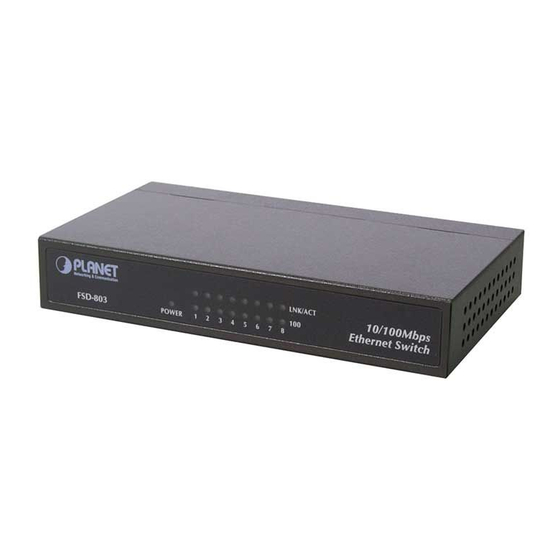
Page 11: Chapter 3 Identifying External Components
Chapter 3 Identifying External Components This section identifies all the major external components of the hub. Both the front and rear panels are shown, followed by a description of each panel feature. The indicator panel is described in detail in the next chapter. Front Panel The figure below shows the front panels of the switches. -
Page 12: Rear Panel
LED Indicator Panel , refer to the LED Indicator section for detailed information about each of the hub’s LED indicators. Rear Panel Rear panel of SW-500, SW-800, FSD-503 and FSD-803 Power is supplied through an external AC power DC Power adapter. -
Page 13: Led Indicators
use ordinary straight -through twisted-pair cables to Jacks: connect user machines and servers to the hub through them. If you need to connect another device with an MDI-X jack, such as another hub or an Ethernet switch, you should use a crossover cable, or make the connection using the MDI-X jack (described below). - Page 14 This LED indicator light green when a Fast Ethernet 100Mbps station is connected. It remains OFF if an Ethernet station is connected. This LED indicator light amber when a respective port is in full duplex (FDX) mode. Otherwise, it is OFF for half duplex (HDX) operations.
-
Page 15: Chapter 4 Connecting The Switch
Chapter 4 Connecting The Switch This chapter describes how to connect the Switch to your Fast Ethernet network. PC to Switch A PC can be connected to the Switch via a two -pair Category 3, 4, 5 UTP/STP straight cable. The PC (equipped with a RJ-45 10/100Mbps phone jack) should be connected to any of the 5/ numbered port. -
Page 16: Hub Without Uplink (Mdi-Ii) Port
B. 100BASE-TX Hub For a 100BASE-TX hub, the Switch LED indicators should light up as the following: FDX /COL LED indicator is OFF. LINK/ACT,100 Speed LED indicators are light green. Hub without Uplink (MDI-II) port If a hub is not equipped with an Uplink (MDI -II) port, connection can be made using either straight cable or crossover cable. -
Page 17: Switch To Switches (Other Devices)
Switch to Switches (other devices) The Switch can be connected to another switch or other devices (routers, bridges, etc.) via a two-pair Category 3, 4, 5 UTP/STP straight or crossover cable. A Using straight cable When using straight cable, this is done from the Uplink (MDI-II) port of the Switch (Switch A) to any of the 10Mbps or 100Mbps (MDI-X) port of the other switch (switch B) or other devices. -
Page 18: Appendix A Technical Specifications
Appendix A Technical Specifications Standards IEEE 802.3 10Base-T Ethernet IEEE 802.3u 100 Base-TX Fast Ethernet Protocol CSMA/CD Data Transfer Rate Ethernet: 10Mbps (half duplex), 20Mbps (full duplex) Fast Ethernet: 100Mbps (half duplex), 200Mbps (full duplex) Topology Star Network Cables 10BASET: 2-pair UTP Cat. 3,4,5 (100 m), EIA/TIA- 568 100-ohm STP (100 m) 100BASE-TX: 2-pair UTP Cat. - Page 19 EMI: FCC Class A, CE Performance Transmit Method: Store-and-forward RAM Buffer: 128K bytes Filtering Address Up to 1K entries per device Table: Packet 10Mbps Ethernet: 14,880/pps Filtering/Forwarding 100Mbps Fast Ethernet: 148,800/pps Rate: Address Automatic update Learning:...
-
Page 20: Appendix B Rj-45 Pin Specification
Appendix B RJ-45 Pin Specification When connecting your 10/100Mbps Ethernet Switch to another switch, a bridge or a hub, a modified crossover cable is necessary. Please review these products for matching cable pin assignment. The following diagram and tables show the standard RJ-45 receptacle/connector their assignments... - Page 21 The following shows straight cable and crossover cable connection: Straight cable for Switch (Uplink MDI-II port) to switch/Hub or other devices connection Crossover cable for Switch (MDI-X port) to switch/hub or other network devices (MDI-X port) connection...
-
Page 22: Appendix C Switch Operation
Appendix C Switch Operation Address Table The Switch is implemented with an address table. This address table composed of many entries. Each entry is used to store the address information of some node in network, including MAC address, port no, etc. The information comes from the learning process of Ethernet Switch. -
Page 23: Store-And-Forward
Store-and-Forward Store-and-Forward type packet-forwarding techniques. A Store-and-Forward Ethernet Switch stores the incoming frame in an internal buffer, do the complete error checking before transmission. Therefore, no error packets occurrence, it is the best choice when a network needs efficiency and stability. The Switch scans the destination address from the packet header, searches the routing table provided for the incomi ng port and forwards the packet, only if required. - Page 24 100Base-TX devices can connect with the 100Base-TX port in either Half- or Full-Duplex mode. If attached device is: 100Base-TX port will set to: • 10Mbps, no 10Mbps auto-negotiation • 10Mbps, with 10/20Mbps (10Base-T/Full-Duplex) auto-negotiation • 100Mbps, no 100Mbps auto-negotiation • 100Mbps, with 100/200Mbps (100Base-TX/Full-Duplex) auto-negotiation...