
Related Manuals for Planet sgsw-2620


Summary of Contents for Planet sgsw-2620
- Page 1 24-Port 10/100Mbps + 2 Gigabit Ethernet Stackable Switch SGSW-2620 User’s Manual - 1 -...
-
Page 2: Fcc Warning
PLANET has made every effort to ensure that this User’s Manual is accurate; PLANET disclaims li- ability for any inaccuracies or omissions that may have occurred. -
Page 3: Table Of Contents
3.2.4 SNMP Management ............................13 3.3 A IP A ......................13 SSIGNING AN DDRESS TO THE WITCH 3.4 L SGSW-2620 .......................... 13 OGGING ON TO THE 4. CONSOLE INTERFACE............................14 4.1 CONNECT TO PC ..............................14 4.2 L ................................. 15 OGIN IN 4.3 G .............................. - Page 4 6.2 L ................................112 EARNING 6.3 F & F ..........................112 ORWARDING ILTERING 6.4 S ............................112 TORE ORWARD 6.5 A ............................. 112 EGOTIATION 7.TROUBLESHOOTING ............................113 APPENDIX A NETWORKING CONNECTION ..................... 114 ‘ A.1 S RJ-45 P ........................114 WITCH SSIGNMENTS A.2 10/100M...
-
Page 5: Introduction
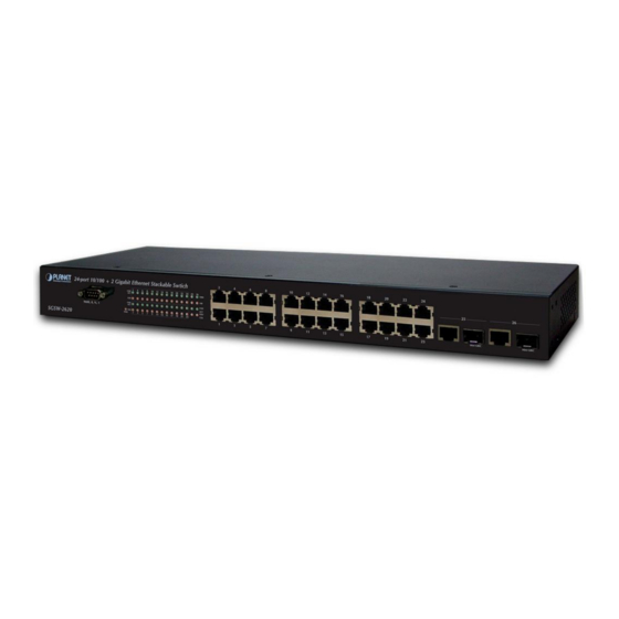
200Mbps of throughput in full-duplex mode. Each 1000M port can support up to 2Gbps in Full-duplex mode. The front panel of SGSW-2620 provides LEDs for easy recognition of the switch operation status and for troubleshooting. These LED indicators display the power status for the system and LNK/ACT, FDX LED for each10/100M port. -
Page 6: Features
1.3 Features Comply with the IEEE802.3 Ethernet, IEEE802.3u Fast Ethernet and IEEE802.3ab, IEEE802.3z Gigabit ◆ Ethernet standard. 24-Port 10/100Mbps Ethernet ports ◆ 2 10/100/1000Mbps ports and 2-SFP Mini-GBIC interfaces ◆ Featured Store-and-Forward mode at wire-speed filtering and forwarding rates ◆ Hardware based 10/100Mbps, half / full-duplex and 1000Mbps full duplex mode, flow control and ◆... -
Page 7: Specification
1.4 Specification Product SGSW-2620 Hardware Specification 10/100/Base-TX Ports 10/100/1000Base-T Ports SFP Mini-GBIC interfaces Switch Processing Scheme Store-and-Forward 8.8Gbps Switch fabric Throughput (packet per second) 6.547Mpps Address Table 8K entries Share data Buffer 3Mbits Back pressure for half duplex, IEEE 802.3x Pause Frame for full duplex... -
Page 8: Hardware Description
This section describes the hardware features of SGSW-2620. For easier management and control of the Switch, familiarize yourself with its display indicators, and ports. Front panel illustrations in this chapter display the unit LED indicators. Before connecting any network device to the SGSW-2620, read this chapter carefully. There are following option module for expansion:... -
Page 9: Rear Panel
2.2 Rear Panel The rear panel of the SGSW-2620 indicates an AC inlet power socket, which accepts input power from 100 to 240VAC, 0.8A, 50-60Hz. Figure 2-2: SGSW-2620 Switch rear panel Power Notice: 1. The device is a power-required device, it means, it will not work till it is powered. If your networks should active all the time, please consider using UPS (Uninterrupted Power Supply) for your device. - Page 10 1. Place the SGSW-2620 on a smooth surface or fasten the mounting brackets purchased separately with the provided screws in a standard 19” rack. 2. Connect the power cord to the power inlet socket of SGSW-2620 and the other end into the local power source outlet.
- Page 11 Figure 2-4 Mounting the Switch in a Rack Connecting end node or hub or switch Step6: Proceed with the steps 2 and steps 3 of section 2.3.2 to connect the network cabling and supply power to your Switch. - 11 -...
-
Page 12: Switch Management
- Using an SNMP Network Management Station. 3.2.1 Local Console Management You can manage the SGSW-2620 locally by connecting a VT100 terminal, or a personal computer or workstation with terminal emulation software, to the Switch serial port. The terminal or workstation connects to the Switch serial port using a null modem cable that has the appropriate connectors on each end. -
Page 13: Remote Console Management
Remote Console Management and SNMP Network Management. 3.4 Logging on to the SGSW-2620 When you log on to the SGSW-2620 console port for the first time, a sign-on string appears and you are prompted for a console login user name and password. -
Page 14: Console Interface
RS-232 serial cable Use the bundled RS-232 serial cable and attach the 9-pin female connector to the male connector on the SGSW-2620. Plug the other side of this cable to your PC. Hyper Terminal In Windows 98/2000/ME/XP, launch “HyperTerminal”, create a new connection, and adjust settings as below: §... -
Page 15: Login In
When a List item is performed, the Space key starts, the selection and scrolls through the available choices. Return to the actions menu. Table 4-1 General Guideline within the Menu 4.4 Main Menu screen After login the SGSW-2620, the main menu screen shows as below. Figure 4-3 SGSW-2620 Main Menu screen - 15 -... -
Page 16: Status And Counters
4.4.2. Explained on Protocol Related Configuration: to configure the protocol function of SGSW-2620. Explained on section 4.4.3. System Reset Configuration: to reboot or reset the SGSW-2620 to factory default mode. Explained on section 4.4.4. Logout: section 4.4.5. allow to logout the SGSW-2620 console interface. Explained in 4.4.1 Status and Counters... - Page 17 Display per port security status. Table 4-2 Descriptions of the Port Status screen Objects 4.4.1.2 Port Counters Display the traffic counters on each port of SGSW-2620, the Port Counters screen in Figure 4-6 pears. Select the <Refresh> to get latest port counter information and choose <Clear> to set the port counter information back to 0.
-
Page 18: Switch Configuration
4.4.1.3 System Information Display the System information of SGSW-2620, the System Information screen in Figure 4-7 appears. Figure 4-7 System Information screen 4.4.1.4 Main Menu Return to main menu screen. 4.4.2 Switch Configuration From the Switch Configuration screen (see Figure 4-8), highlight Switch Configuration and press Enter. - Page 19 Username Configuration: please refer to chapter 4.4.2.1.3. Password Configuration: please refer to chapter 4.4.2.1.4. Previous Menu: please refer to chapter 4.4.2.1.5. 4.4.2.1.1 Device Information Press “Edit” to edit the device information of SGSW-2620, the device information screen in Figure 4-11 appears.
- Page 20 5. Press any key for return to previous menu. 4.4.2.1.2 IP Configuration Press, ”Edit” to disable or enable the DHCP Client function and modify the IP address, Subnet Mask, Gateway of SGSW-2620. The IP configuration screen in Figure 4-13 appears.
- Page 21 After setup completed, press “ESC” and choose “Save” to save the current configuration. The following screen in Figure 4-14 appears. Figure 4-14 IP Configuration save successful screen Please reboot the SGSW-2620 to take effect for your current IP configuration. Notice: the default IP address of SGSW-2620 is 192.168.0.1. - 21 -...
- Page 22 4.4.2.1.3 User Name Configuration Press, “Edit” to input the new user name, after setup completed, press “ESC” and choose “Save” to save the current configuration. The following screen in Figure 4-15 & 4-16 appears. Figure 4-15 Edit User Name Configuration screen Figure 4-16 User Name Configuration save successfully screen Press any key for return to previous menu.
- Page 23 4.4.2.1.4 Password Configuration Allow user to modify the password of SGSW-2620. Figure 4-17 Password Configuration screen Modify the password procedure: 1. Enter old password: empty (Default is admin) 2. Enter new password: * * * * * (New password) 3. Enter again: * * * * * (New password) 4.
- Page 24 4.4.2.2 Port Configuration From the Switch Configuration sub-screen (see Figure 4-9), highlight Port Configuration and press enter. The Port Configuration screen in Figure 4-18 appears. Table 4-3 describes the port configura- tion objects of switch. Figure 4-18 Port Configuration screen Object Description Type...
- Page 25 Figure 4-20 Port Configuration save successfully screen 4.4.2.3 Trunk Configuration From the Switch Configuration sub-screen (see Figure 4-9), highlight Trunk Configuration and press enter. The Trunk Configuration screen in Figure 4-21 appears. Figure 4-21 Trunk Configuration screen Press ” Edit” to configure the trunk group. After setup completed, press “ESC” and choose “Save” to save the current configuration.
- Page 26 Figure 4-23 Trunk Configuration save successfully screen 4.4.2.4 Port Mirroring Configuration From the Switch Configuration sub-screen (see Figure 4-9), highlight Port Mirroring Configuration and press enter. The Port Mirroring Configuration screen in Figure 4-24 appears. Figure 4-24 Port Mirroring Configuration screen Press ”Edit”...
- Page 27 Figure 4-25 Port Mirroring Configuration save successfully screen Press any key for return to previous menu. 4.4.2.5 VLAN Configuration From the Switch Configuration sub-screen (see Figure 4-9), highlight VLAN Configuration and press enter. The VLAN Configuration screen in Figure 4-26 appears.
- Page 28 802.1Q VLAN screen in Figure 4-28 appears. The SGSW-2620 supports up to 256 VLAN groups and maximum PVID is 4094. The setting sequence is choose the VLAN ID Range first then assign the corresponding Port VLAN ID on each port.
- Page 29 10. 2304~2559. 11. 2560~2815. 12. 2816~3071. 13. 3072~3327. 14. 3328~3583. 15. 3584~3839. 16. 3840-4094. The description of other items from the 802.1Q VLAN configure are shown as below: VLAN ID: input the PVID based on the current VLAN ID Range and VLAN setting. Ingress Filter: it matches that Ingress Filtering Rule 1, only forward packets with VLAN ID matching this port’s configured VLAN ID.
- Page 30 Figure 4-30 802.1Q VLAN Configure save successfully screen Press any key for return to previous menu. Press space bar switch to Port Based in VLAN mode. The screen in Figure 4-31 appears. After setup completed, press “ESC” and choose “Save” to save the current configuration. The fol- lowing screen in Figure 4-32 4-33...
- Page 31 1. Security VLAN setting: allow user to disable or enable the security VLAN group. When enable the security VLAN group function, only the member ports in this VLAN group can access to the SGSW-2620. After configured the security VLAN group and still can continue to create other IEEE 802.1Q VLAN groups.
- Page 32 Figure 4-36 Add a Port-based VLAN Group screen Create a port-based VLAN group procedure: 1. Press “Edit” to input the VLAN name and Group ID. 2. Under Port-based VLAN mode. Set Member or no (not belong to any VLAN group) of each port. 3.
- Page 33 5. After setup completed, press “ESC” and choose “Save” to save the current configuration. The screens in Figure 4-40& 4-41 & 4-42 appear. Figure 4-38 Edit an existence VLAN Group screen Figure 4-39 Edit an existence VLAN Group screen Figure 4-40 Edit an existence VLAN Group completed and save successfully screen - 33 -...
- Page 34 Figure 4-41 Delete an existence VLAN Group screen Figure 4-42 Delete an existence VLAN Group successfully screen Press any key for return to previous menu. 4.4.2.5.4 Group Sorted Mode Allow choosing existence VLAN groups sorted mode by name or VLAN ID. The screen in Figure 4-43 appears.
- Page 35 Press any key for return to previous menu. 4.4.2.5.5 Previous Menu Return to Switch Configuration sub-screen. 4.4.2.6 Priority Configuration Displays the options available for assigning High and Low priority to each port of SGSW-2620. From the Switch Configuration sub-screen (see Figure 4-9), highlight Priority Configuration and press enter.
- Page 36 Figure 4-45 Priority Configuration screen Press, ” Edit” to assigning High or Low priority on each port and choose different item from Qos Mode. After setup completed, press “ESC” and choose “Save” to save the current configuration. The screen Figure 4-46 appears.
- Page 37 Figure 4-47 MAC Address Configuration screen This sub-menu contains 3 items. Static MAC Address: please refer to chapter 4.4.2.7.1. Filtering MAC Address: please refer to chapter 4.4.2.7.2. Previous Menu: please refer to chapter 4.4.2.7.3. 4.4.2.7.1 Static MAC Address Add a static MAC address, it will remains in the switch MAC address table, regardless of whether the device is physically connected to the switch.
- Page 38 Figure 4-49 Static MAC Address Configuration save successfully screen Press any key for return to previous menu. Edit Static Mac address procedure: 1.Press “Edit”. 2.Choose the MAC address that want to edit and press “Enter”. 3.Press “Edit” to edit the existence MAC address. 4.After setup completed, press “ESC”...
- Page 39 Figure 4-51 Filter MAC Address Configuration save successfully screen Press any key for return to previous menu. Edit Filter Mac address procedure: 1.Press “Edit”. 2.Choose the MAC address that want to edit and press “Enter”. 3.Press, “Edit” to edit the existence MAC address. 4.After setup completed, press “ESC”...
- Page 40 The valid range is 1~255 ms. Collisions Retry Forever: Disable – In half duplex, if happens collision, the SGSW-2620 will retry 48 times and then drop frame. Enable – In half duplex, if happens collision, the SGSW-2620 will retry forever.
-
Page 41: Protocol Related Configuration
And, the Rapid Spanning Tree Protocol (RSTP) is an evolution of the Spanning Tree Protocol and provides for faster spanning tree convergence after a topology change. The SGSW-2620 provides IEEE 802.1D Spanning Tree and IEEE 802.1W Rapid Spanning Tree function. The RSTP Configuration sub-screen in Figure 4-54 appears. - Page 42 This sub-menu contains five items: Set RSTP Mode: please refer to chapter 4.4.3.1.1. System Configuration: please refer to chapter 4.4.3.1.2. Per port Setting: please refer to chapter 4.4.3.1.3. Per port Status: please refer to chapter 4.4.3.1.4. Previous Menu: please refer to chapter 4.4.3.1.5. 4.4.3.1.1 Set RSTP Mode Provide disable or enable STP or RSTP function.
- Page 43 4.4.3.1.2 System Configuration Allow modify the RSTP system configuration and view the Root Bridge Information. The System Configuration screen in Figure 4-57 appears. Figure 4-57 RSTP system configuration screen Setup procedure: 1. Press “ Edit” to modify the Rapid Spanning Tree Parameters. 2.
- Page 44 Allow edit per port STP configuration. The RSTP Per Port Setting screen in Figure 4-59 appears. Figure 4-59 RSTP Per Port Setting screen Setup procedure: 1. Press “ Edit” to modify the path cost and priority on each port. 2. After setup completed, press” ESC” and choose “Save” to save the current configure. The screen in Figure 4-60 appears.
- Page 45 Display the RSTP per port status. The screen in Figure 4-61appears, table 4-4 describes the Per Port Status Figure 4-61 RSTP Per Port status screen Object Description Role Display the port role in the Spanning Tree Protocol. State Display the port current status. Path Cost Display the port path cost value.
- Page 46 Community Strings: please refer to chapter 4.4.3.2.2. Trap Managers: please refer to chapter 4.4.3.2.3. Previous Menu: please refer to chapter 4.4.3.2.4. 4.4.3.2.1 System Options Allow inputting the system name, system contact and system location. The SNMP System Options screen in Figure 4-63 appears.
- Page 47 Figure 4-65 SNMP Community Strings screen Setup procedure: 1. Press “Add” to enter into “Add SNMP community” screen, then press “Edit” a new community name and adjust the write access mode. 2. After setup completed, press ”ESC” and choose “Save” to save the current configure. The screen in Figure 4-66 &...
- Page 48 Edit Community Name procedure: 1.Press “Edit”. 2.Choose the Community Name that want to edit and press “Enter”. 3.Press “Edit” to edit the existence Community Name and press “Space” key to change the access right from Write Access function. 4.After setup completed, press “ESC” and choose “Save” to save the current configuration. Delete Community Name procedure: 1.Press “Delete”.
- Page 49 Figure 4-70 SNMP Trap managers save successfully screen Press any key for return to previous menu. Edit Trap Managers procedure: 1.Press “Edit”. 2.Choose the Community Name that want to edit and press “Enter”. 3.Press “Edit” to edit the existence IP address and Community Name. 4.After setup completed, press “ESC”...
- Page 50 Figure 4-71 LACP Configuration screen This subnet menu contains four items: Working Ports: please refer to chapter 4.4.3.3.1. State Activity: please refer to chapter 4.4.3.3.2. Group Status: please refer to chapter 4.4.3.3.3. Previous Menu: please refer to chapter 4.4.3.3.4. 4.4.3.3.1 Working Ports Allow editing the LACP working ports configuration.
- Page 51 Notice: before to enable the LACP support, please assure and add a trunk group from Trunk function. 4.4.3.3.2 State Activity Allow to set LACP port state activity of each port. The working ports screen in Figure 4-73 appears. Figure 4-73 LACP port state Active configuration screen Setup procedure: 1.
- Page 52 Figure 4-74 LACP Group Status screen 4.4.3.3.4 Previous Menu Return to Protocol Related Configuration screen. 4.4.3.4 IGMP/GVRP Configuration Provide disable or enable the IGMP and GVRP function. The IGMP/GVRP Configuration screen in Figure 4-75 appears. Figure 4-75 IGMP/GVRP Configuration screen Setup procedure: 1.
- Page 53 Figure 4-76 IGMP/GVRP Configuration save successfully screen Press any key for return to previous menu. 4.4.3.5 802.1x Configuration Provide 802.1x configuration. The 802.1x Configuration sub-screen in Figure 4-77 appears. Figure 4-77 802.1x Configuration sub-screen This subnet menu contains five items: 802.1x Setup: please refer to chapter 4.4.3.5.1.
- Page 54 4.4.3.5.1 802.1x Setup Provide disable or enable the IEEE 802.1x function. The screen in Figure 4-78 appears. Figure 4-78 802.1x Setup screen 802.1x Setup procedure: 1. Press “Edit” and use “Space” key to disable or enable the 802.1x function. 2. After setup completed, press” ESC” and choose “Save” to save the current configure. The screen in Figure 4-79 appears.
- Page 55 4.4.3.5.2 System Configuration Allow modify the 802.1x system configuration. The screen in Figure 4-80 appears. Figure 4-80 802.1x System Configuration screen Setup procedure: 1. Press “Edit” 2. Radius Server IP: input the Radius Server IP address. 3. Shared Key: set an encryption key for using during authentication sessions with the specified radius server.
- Page 56 4.4.3.5.3 Per Port Setting Allow modify the 802.1x Per Port Setting, the State provides Disable, Accept, Reject and Authorize. Use “Space” key change the state mode. The screen in Figure 4-82 appears. Figure 4-82 802.1x Per Port Setting screen After setup completed, press” ESC” and choose “Save” to save the current configure. The screen in Figure 4-83 appears.
- Page 57 Allow modify the 802.1x Misc configuration. The screen in Figure 4-84 appears. Figure 4-84 802.1x Misc Configuration screen Setup procedure: 1. Press “Edit”. 2. Quiet Period: set the period during which the port doesn’t try to acquire a supplicant. The available ranges are 0-65535 and default mode is 60.
-
Page 58: System Reset Configuration
4.4.3.6 Previous Menu Return to the main menu screen. 4.4.4 System Reset Configuration Provide reset to switch to default mode, reboot the Switch and firmware upgrade through TFTP server. The screen in Figure 4-86 appears. Figure 4-86 System Reset Configuration screen This subnet menu contains four items: Factory Default: please refer to chapter 4.4.4.1. - Page 59 Figure 4-88 Resetting Switch screen Figure 4-89 Resetting Switch screen 4.4.4.2 System Reboot Provide restart the Switch. The screen in Figure 4-90 appears. Figure 4-90 System Reboot screen - 59 -...
- Page 60 Figure 4-92 TFTP Update Firmware screen Setup procedure: 1. Download the latest firmware from Planet website, and copy the firmware version image file to the TFTP server. 2. Press “Edit” 3.TFTP Server IP: input the IP address of the workstation that install TFTP server.
- Page 61 6. When the image file download completed, Restart switch, please reboot the Switch for new firmware. Figure 4-93 TFTP Update Firmware process screen 4.4.4.3.2 Restore Configuration Provide restore the configuration through the TFTP server method, the screen in Figure 4-94 appears.
- Page 62 Figure 4-95 TFTP Restore Configuration process screen 5. When the image file download completed, please reboot the Switch for new configuration. 4.4.4.3.3 Backup Configuration Provide backup the configuration through the TFTP server method, the screen in Figure 4-96 appears. Figure 4-96 TFTP Backup Configuration screen Setup procedure: 1.
-
Page 63: Logout
4.4.4.3.4 Previous Menu Return to Protocol Related Configuration screen. 4.4.4.4 Previous Menu Return to the main menu screen. 4.3.5 Logout Provide logout the Switch. The screen in Figure 4-98 & 4-99 appears. Figure 4-98 SGSW-2620 Logout screen - 63 -... - Page 64 Figure 4-99 SGSW-2620 Login screen - 64 -...
-
Page 65: Web Management
(RS232 port) and use this IP address to configure SGSW-2620 through the Telnet and Web interface. Or modify your PC’s IP domain to the same with SGSW-2620 then use the default IP address (192.168.0.1) to remote configure SGSW-2620 through the Telnet and Web interface. -
Page 66: Port Status
Auto-negotiation state of each port on SGSW-2620. “Config” means the mode that Negotiation user configured. “Actual” means the current mode on each port. Display the speed state of each port on SGSW-2620. “Config” means the duplex mode Speed Duplex that user configured. “Actual” means the current duplex mode on each port. -
Page 67: Port Statistics
Also, it is helpful to troubleshooting network problems. Please click clear button to clean all counts on each port. The screen in Figure 5-5 appears. Figure 5-5 SGSW-2620 Port Statistics Web Page screen - 67 -... -
Page 68: Administrator
5-4 Administrator This section contains management function on SGSW-2620 and the screen in Figure 5-6 appears. Figure 5-6 SGSW-2620 Administrator Web Page screen This management function is shown as below: IP Configuration: please refer to section 5.4.1. Switch Settings: please refer to section 5.4.2. -
Page 69: Ip Configuration
5.4.1 IP Configuration This section allows modify the IP address, Subnet Mask, Gateway of SGSW-2620 and also provide DHCP Client function. The screen in Figure 5-7 appears. Figure 5-7 SGSW-2620 modify IP Address Web Page screen After modifying the new IP address, Subnet Mask, Gateway, please click “Apply” button then the following appears. -
Page 70: Switch Settings
Figure 5-9 SGSW-2620 IP Address help Web Page screen Click “Close” to close this screen. 5.4.2 Switch Settings This function provides three settings on SGSW-2620, the available items are Basic, Advanced, and Misc Config. The Switch Setting screen in Figure 5-10 appears. - Page 71 Display the MAC address of SGSW-2620. Module Display the information of port 25.26. Table 5-2 Descriptions of the SGSW-2620 Switch Settings Basic Web Page screen Objects 5.4.2.2 Advanced This function provides two functions – MAC Table Address Entry and Priority Queue Service. The screen in Figure 5-11 appears.
- Page 72 0~7 priority level can map to high or low queue. ority Levels Table 5-3 Descriptions of the SGSW-2620 Switch Settings Advanced Web Page screen Objects Notice: Make sure of “Max bridge transit delay bound control” is enabled before enable Delay Bound, because Enable Delay Bound must be work under “Max bridge transit delay bound control is...
- Page 73 Figure 5-12 SGSW-2620 Advanced help Web Page screen Click “Close” to close this screen. 5.4.2.3 Misc Config The screen in Figure 5-13 appears. Table 5-4 descriptions the Misc Config objects of switch. Figure 5-13 SGSW-2620 Switch Settings Misc Config Web Page screen - 73 -...
- Page 74 Enable Mode: enables the switch to be the IGMP Querier. Disable Mode: disables all other switches from being the IGMP Querier. Table 5-4 Descriptions of the SGSW-2620 Switch Settings Misc Config Web Page screen Objects appears. Click “Close” to close this screen.
- Page 75 3. The following topology must be set when the IP address of the switch is not the smallest in the subnet. The network will cause a multi-cast storm from the IGMP client report if it is in Auto mode. All switches must be in disable mode when the VOD server is configured for IGMP Querier.
-
Page 76: Console Port Information
Figure 5-14 appears. Figure 5-14 SGSW-2620 Console Port Information Web Page screen 5.4.4 Port Controls This section introduces detail settings of per port on SGSW-2620. The screen in Figure 5-15 appears. Table 5-5 descriptions the Port Controls objects of switch. -
Page 77: Trunking
MAC addresses screen to define a list of MAC addresses that can use the secure port. Table 5-5 Descriptions of the SGSW-2620 Switch Port controls Web Page screen Objects 5.4.5 Trunking This section displays the screen for trunking a group of ports together to speed up data transmission. The available items are Aggregator Setting. - Page 78 Select the ports to remove the trunking group. Click “Apply” to take effect. Remove To delete trunk group. Click “Delete” to take effect. Delete Table 5-6 Descriptions of the SGSW-2620 Switch Aggregator Setting Web Page screen Objects Please click” Help” button; the following screen in Figure 5-17 appears.
- Page 79 This function allows viewing the LACP aggregator information. The screen in Figure 5-18 appears. Figure 5-18 SGSW-2620 Trunking Aggregator information Web Page screen 5.4.5.3 State Activity This function allows setup the LACP aggregator and configure port state activity. Table 5-7 descriptions the State Activity objects of switch.
- Page 80 The port does not automatically sends LACP protocol packets and only respond when it enable Active) receives LACP protocol packets from the opposite device Table 5-7 Descriptions of the SGSW-2620 Switch State Activity Web Page screen Objects Notice: * A link having either two active LACP ports or one active port can perform dynamic LACP trunk- ing.
-
Page 81: Forwarding And Filtering
Figure 5-21 SGSW-2620 Forwarding and Filtering Web Page screen 5.4.6.1 IGMP Snooping SGSW-2620 support IP multicast and allow enable IGMP protocol on Forwarding and Filtering page from the web interface. This web page provide IGMP Snooping information, you can see different multicast group, VID and member port. - Page 82 Switch. This function make the Switch can relearn device’s MAC Address when the device is disconnected or power-off and active in the network again. The screen in Figure 5-23 appears. Figure 5-23 SGSW-2620 Static MAC Addresses Web Page screen - 82 -...
- Page 83 VLANs. Type the VID (tag-based VLANs) to associate with the MAC address. 6. Click “Add” to take effect. Please click” Help” button; the following screen in Figure 5-24 appears. Figure 5-24 SGSW-2620 Static MAC Addresses help Web Page screen Click “Close” to close this screen. - 83 -...
- Page 84 5.4.6.3 MAC Filtering MAC filtering allows the SGSW-2620 to drop unwanted traffic. Traffic is filtered based on the destination ad- dresses. For example: if your network is congested because of high utilization from one MAC address, you can filter all traffic transmitted from that MAC address. The screen in Figure 5-25 appears.
-
Page 85: Vlan Configuration
VLAN receive traffic from the same VLAN members. Basically, creating a VLAN from SGSW-2620 is logically equivalent of reconnecting a group of network device to another Layer 2 Switch. However, the entire network device is still plug into the same Switch physically. - Page 86 After enable the port-based VLAN function, packets can go among only members of the same VLAN group. Notice: all unselected ports are treated as belonging to another single VLAN. If the port-based VLAN enabled, the VLAN-tagging is ignored. Figure 5-28 SGSW-2620 Port Based VLAN Web Page screen - 86 -...
- Page 87 5. If the port-based VLAN groups list over one page, please click “Next Page” to view other VLAN groups on other page. 6. Use “Delete” button to delete unwanted port-based VLAN groups 7. Use “ Edit” button to modify existing port-based VLAN groups. Figure 5-29 SGSW-2620 Port Based VLAN setting Web Page screen - 87 -...
- Page 88 Figure 5-30 SGSW-2620 Port Based VLAN setting successful Web Page screen Please click” Help” button; the following screen in Figure 5-31 appears. Figure 5-31 SGSW-2620 Port Based VLAN setting help Web Page screen Click “Close” to close this screen. - 88 -...
- Page 89 GVRP enabled, you can send a GVRP request using the VID of a VLAN defined on the switch; the switch will automatically add that device to the existing VLAN. Figure 5-32 SGSW-2620 IEEE 802.1Q VLAN Web Page screen Basic: Create a new 802.1Q VLAN group and add tagged member ports procedure:...
- Page 90 Figure 5-33 SGSW-2620 IEEE 802.1Q VLAN Web Page screen Figure 5-34 SGSW-2620 IEEE 802.1Q VLAN Web Page screen 9. If the 802.1Q VLAN groups list over one page, please click “Next Page” to view other VLAN groups on other page.
- Page 91 Figure 5-35 SGSW-2620 IEEE 802.1Q VLAN Help Web Page screen Click “Close” to close this screen. Port VID: In order for an end station send packets to different VLANs. Itself has to be either capable of tagging packets it sends with VLAN tags or attached to a VLAN-aware bridge that is capable of classifying and tagging the packet with different VLAN ID based on default PVID and other packet information.
- Page 92 VLAN ID will be in the same VLAN group. Range After setup completed, click “Apply” button to take effect. Apply Reset to factory mode by click “Default” button Default Table 5-8 Descriptions of the SGSW-2620 Port VLAN ID Web Page screen Objects - 92 -...
-
Page 93: Spanning Tree
Enter a value between 4 through 30. Time Table 5-9 Descriptions of the SGSW-2620 Spanning Tree System Configuration Web Page screen Objects After setup completed, please click “Apply” button to take effect. - Page 94 Per Port Configuration: This function allows configuring path cost and priority on each port of SGSW-2620. The screen in Figure 5-38 appears. Table 5-10 describes the Per Port Configuration objects of switch. Figure 5-38 SGSW-2620 Spanning Tree Per Port Configuration Web Page screen...
- Page 95 Figure 5-39 SGSW-2620 Spanning Tree Help Web Page screen Click “Close” to close this screen. - 95 -...
-
Page 96: Port Mirroring
5.4.9 Port Mirroring The Port Mirroring is a method for monitor traffic in SGSW-2620 networks. Traffic through ports can be monitored by one specific port. Traffic through the in or out monitored ports will be duplicated into Mirroring port. The screen in Figure 5-40 appears. - Page 97 Figure 5-41 SGSW-2620 Port Sniffer Help Web Page screen Click “Close” to close this screen. - 97 -...
-
Page 98: Snmp
Use this page to define the management stations as trap managers and key in SNMP community strings. It also allows user to define a name, location and contact person for the SGSW-2620. Fill in the system options data and click “Apply” button to update the change of this page. The screen in Figure 5-43 appears. - Page 99 Figure 5-44 Community Strings Web Page screen Please check the detail description of parameters as below: RO / Read Only: enables requests accompanied by this string to display MIB-object information. RW / Read Write: enables requests accompanied by this string to display MIB-object information and set MIB objects.
-
Page 100: Security Manager
Figure 5-46 SNMP Management Help Web Page screen Click “Close” to close this screen. 5.4.11 Security Manager Allow user to modify the User Name and Password of SGSW-2620. The screen in Figure 5-47 appears. Figure 5-47 SGSW-2620 Security Manager Web Page screen 1. -
Page 101: Configuration
This key must match the encryption key used on the Radius Server. Set the identifier for the radius client. NAS, Identifier Table 5-12 Descriptions of SGSW-2620 802.1x Configuration System Configuration Web Page screen Ob- jects After setup completed, please click “Apply” button to take effect. - Page 102 Figure 5-49 802.1x Configuration Help Web Page screen Click “Close” to close this screen. Per Port Configuration: The screen in Figure 5-50 appears. Table 5-13 describes the System Configuration objects of switch. Figure 5-50 SGSW-2620 802.1x Configuration Per Port Configuration Web Page screen - 102 -...
- Page 103 Supplicant and the authentication server. Disable: The specified port is required to be held in the Authorized state. Table 5-13 Descriptions of SGSW-2620 802.1x Configuration Per Port Configuration Web Page screen Ob- jects After setup completed, please click “Apply”...
-
Page 104: Tftp Update Firmware
The following menu options provide some system control functions to allow user to update latest firmware and remotely reboot SGSW-2620 system. The screen in Figure 5-52 appears. Figure 5-52 SGSW-2620 TFTP Update Firmware Web Page screen Firmware update requirements: 1. The latest firmware version of SGSW-2620. 2. SGSW-2620. -
Page 105: Configuration Backup
5-6 Configuration Backup This option allows you to backup the SGSW-2620’s configuration into a file. The screen in Figure 5-54 appears. Figure 5-54 SGSW-2620 TFTP Configuration Web Page screen TFTP Restore Configuration: Figure 5-55 SGSW-2620 TFTP Restore Configuration Web Page screen Purpose: allow restore the EEPROM value from this function. -
Page 106: Factory Default
Click “Apply” button to save current EEPROM value. appears. Click “Close” to close this screen. Please click” Help” button; the following screen in Figure 5-53 5-7 Factory Default This function provides reset the SGSW-2620 to factory default mode. The screen in Figure 5-57 appears. - 106 -... -
Page 107: System Reboot
Figure 5-57 SGSW-2620 Reset Switch Web Page screen 5-8 System Reboot This function allows reboot the SGSW-2620. The screen in Figure 5-58 appears. - 107 -... -
Page 108: Panel List
Figure 5-58 SGSW-2620 Reboot Switch Web Page screen 5-9 Panel List This function will display the SGSW-2620 web panel. When the SGSW-2620 is in stacking status, it display the slaves web panel. When the SGSW-2620 is stand-alone status, it display itself web panel. Please click the port on the web panel to check port current information. -
Page 109: Ip Stacking
Figure 5-59 SGSW-2620 Panel List Web Page screen 5-10 IP Stacking This function allows SGSW-2620 stack up to 8 stackable switches as a unit group. The screen in Figure 5-60 appears. Figure 5-60 SGSW-2620 IP Stacking Web Page screen IP Stacking setup procedure: Click “IP Stacking”... - Page 110 Figure 5-61 SGSW-2620 IP Stacking Web Page screen After you have configured the stacking function, use Cat. 5 cable to connect each SGSW-2620 in the stacking group. And wait for few minutes for the master switch to communicate and collect the data from the slave switches.
- Page 111 Figure 5-62 SGSW-2620 IP Stacking Web Page screen If want to configure one of SGSW-2620 in stacking group, click the hyper link on the top of screen and login to the switch that you want to configure. The screen of the SGSW-2620 that selected in Figure 5-63 appears.
-
Page 112: Switch Operation
No packet loss will occur. 6.5 Auto-Negotiation The STP ports on the SGSW-2620 switch have built-in "Auto-negotiation". This technology automatically sets the best possible bandwidth when a connection is established with another network device (usually at Power On or Reset). Detecting the modes does this and speeds at the second of both devices are con- nected and capable of, both 10Base-T and 100Base-TX devices can connect with the port in either Half- or Full-duplex mode. -
Page 113: Troubleshooting
7.TROUBLESHOOTING This chapter contains information to help you solve problems. If the Switch is not functioning properly, make sure the Ethernet Switch was set up according to instructions in this manual. The Link LED is not lit Solution: Check the cable connection and remove duplex mode of the Switch Some stations cannot talk to other stations located on the other port Solution: Please check the VLAN, port trunking and Port Morroring function that may introduce this kind of problem. -
Page 114: Appendix A Networking Connection
APPENDIX A NETWORKING CONNECTION A.1 Switch‘s RJ-45 Pin Assignments 1000Mbps, 1000Base T Contact MDI-X BI_DA+ BI_DB+ BI_DA- BI_DB- BI_DB+ BI_DA+ BI_DC+ BI_DD+ BI_DC- BI_DD- BI_DB- BI_DA- BI_DD+ BI_DC+ BI_DD- BI_DC- Implicit implementation of the crossover function within a twisted-pair cable, or at a wiring panel, while not expressly forbidden, is beyond the scope of this standard. - Page 115 Figure A-1: Straight-Through and Crossover Cable Please make sure your connected cables are with same pin assignment and color as above picture before deploying the cables into your network. EM-SGSW2620v1 - 115 -...