Planet GSD-802S User Manual
Planet technology 8-port gigabit web smart ethernet switch user's manual
Hide thumbs
Also See for GSD-802S:
- User manual (89 pages) ,
- Quick installation manual (2 pages) ,
- User manual (20 pages)

Related Manuals for Planet GSD-802S


Summary of Contents for Planet GSD-802S
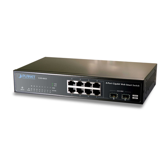
- Page 1 User's Manual GSD-800S GSD-802S 8-Port Gigabit Web Smart Ethernet Switch GSD-802PS 8-Port Gigabit Web Smart PoE Switch...
- Page 2 Copyright © PLANET Technology Corp. 2007. Contents subject to which revision without prior notice. PLANET is a registered trademark of PLANET Technology Corp. All other trademarks belong to their respective owners. Disclaimer PLANET Technology does not warrant that the hardware will work properly in all environments and applications, and makes no warranty and representation, either implied or expressed, with respect to the quality, performance, merchantability, or fitness for a particular purpose.
-
Page 3: Table Of Contents
4.6.2 RSTP Port Configuration... 38 4.6.3 RSTP Status ... 39 4.7 L ... 42 GGREGATION 4.7.1 Port Trunk ... 42 4.7.2 LACP... 43 4.7.3 LACP Status... 45 4.8 IGMP S ... 47 NOOPING User’s Manual of GSD-800S / GSD-802S / GSD-802PS TABLE OF CONTENTS... - Page 4 6. TROUBLESHOOTING... 81 APPENDIX A ... 82 A.1 S ‘ RJ-45 P WITCH SSIGNMENTS A.2 10/100M , 10/100B -TX ... 82 A.3 RJ-45 CABLE PIN ASSIGNMENT User’s Manual of GSD-800S / GSD-802S / GSD-802PS )... 76 ... 82 ... 83...
-
Page 5: Introduction
The section explains the basic layer 2 theories and functions. Appendices It contains cable information of Switch. In the following section, the term “Gigabit Ethernet Switch” means the GSD-800S/GSD-802 and GSD-802PS. User’s Manual of GSD-800S / GSD-802S / GSD-802PS 1. INTRODUCTION... -
Page 6: Product Features
802.1X Port-Base access control, RADIUS ServerAuthentication Static MAC Address assign destination MAC address at specifies port Power over Ethernet (GSD-802PS) Per Port PoE Full power support Powered Device Auto detection Power Interface Protection User’s Manual of GSD-800S / GSD-802S / GSD-802PS ports. -
Page 7: Product Specification
Management Interface Port configuration VLAN Link Aggregation IGMP Snooping Port Mirror SNMP MIBs User’s Manual of GSD-800S / GSD-802S / GSD-802PS GSD-800S GSD-802S 8-Port 10/100/1000Base-T Auto MDI/MDI-X Store-and-Forward 8K entries 176KB On-chip frame buffer Back pressure for half duplex, IEEE 802.3x Pause Frame for full duplex 217 x 135 x 43.5, 1U height... - Page 8 EMI Safety Network Standards Operating Temperature Storage Temperature Operating Humidity Storage Humidity Regulation Compliance User’s Manual of GSD-800S / GSD-802S / GSD-802PS RFC-1573-Interface MIB RFC-2819 RMON MIB (Group 1) FCC Class A, CE IEEE 802.3 Ethernet IEEE 802.3u Fast Ethernet IEEE 802.3ab...
-
Page 9: Installation
User’s Manual of GSD-800S / GSD-802S / GSD-802PS 2. INSTALLATION This section describes the functionalities of Gigabit Ethernet Switch’s components and guides how to install it on the desktop or shelf. Basic knowledge of networking is assumed. Please read this chapter completely before continuing. -
Page 10: Switch Front Panel
2.1.2 Switch Front Panel Figure 2-1 & 2-2 & 2-3 shows a front panel of GSD-800S / GSD-802S and GSD-802PS. 2.1.3 LED Indicators LED of GSD-800S / GSD-802S ■ Color Lights to indicate that the Switch is powered on. Green Lights to indicate that the Switch is successfully connecting to the network at 1000Mbps. -
Page 11: Switch Rear Panel
“RESET” button. 2.1.4 Switch Rear Panel The rear panel of the Gigabit Ethernet Switch indicates an AC inlet power socket, which accepts input power from 100 to 240VAC, 50-60Hz. User’s Manual of GSD-800S / GSD-802S / GSD-802PS... -
Page 12: Install The Switch
UPS (Uninterrupted Power Supply) for your device. It will prevent you from network data loss or network downtime. 2. In some area, installing a surge suppression device may also help to protect your Gigabit Ethernet Switch from being damaged by unregulated surge or current to the Switch or the power adapter. -
Page 13: Rack Mounting
(RKE-10B) is available upon request. Step1: Place the Gigabit Ethernet Switch on a hard flat surface, with the front panel positioned towards the front side. Step2: Attach the rack-mount bracket to each side of the Gigabit Ethernet Switch, with supplied screws attached to the package. -
Page 14: Installing The Sfp Transceiver
Gigabit Ethernet Switch. As the Figure 2-10 appears. Approved PLANET SFP Transceivers PLANET Gigabit Ethernet Switch supports both single mode and multi mode SFP transceiver. The following list of approved PLANET SFP transceivers is correct at the time of publication: ■MGB-SX SFP (1000Base-SX SFP transceiver ) - Page 15 Connect the other end of the cable to a device – switches with SFP installed, fiber NIC on a workstation or a Media Converter.. Check the LNK/ACT LED of the SFP slot on the front of the Gigabit Ethernet Switch. Ensure that the SFP transceiver is operating correctly.
-
Page 16: Switch Management
- Logging on to the Gigabit Ethernet Switch 3.1 Overview This chapter gives an overview of switch management. The Gigabit Ethernet Switch provides a simply WEB browser interface. Using this interface, you can perform various switch configuration and management activities, including:... -
Page 17: Login The Switch
Ethernet connection, make sure the manager PC must be set on same the IP subnet address. For example, the default IP address of the Gigabit Ethernet Switch is 192.168.0.100, then the manager PC should be set at 192.168.0.x (where x is a number between 2 and 254), and the default subnet mask is 255.255.255.0. -
Page 18: Configuration
Gigabit Ethernet Switch from the local LAN. This section indicates how to configure the Gigabit Ethernet Switch to enable its smart function. Notice: The following section will base on the web screens of GSD-800S, for GSD-802S/802PS the display will be the same to GSD-800S. 4.1 Main Menu After a successful login, the main screen appears, the main screen displays the Switch status. - Page 19 User’s Manual of GSD-800S / GSD-802S / GSD-802PS ◆ IGMP Snooping - Enables or disables IGMP Snooping on the device to filter the multicast stream. ◆ Quality of Service – Mapping the packet level to classify the packets priority. ◆ 802.1X Management – Specify ports with network access control.
-
Page 20: System
4.2.1 System Info The System Info page provides information for the current device information. System Info page helps a switch administrator to identify the firmware / hardware version and IP subnet address / DHCP server IP address. The screen in Figure 4-2 appears. -
Page 21: Misc Configuration
Location Name. The Login Timeout is to set the idle time-out for security issue, when there is no action in running the Web Switch Utility and the time is up, you must re-login to Web Switch Utility before you set the Utility. Fill up the IP Address, Subnet Mask and Gateway for the device. - Page 22 After change the default password, if you forget the password. Please press and release the Notice: “Reset” button in the front panel of Gigabit Ethernet Switch, the current setting includes VLAN, will be lost and the Gigabit Ethernet Switch will restore to the default mode.
-
Page 23: Port Configuration
• Port • Mode User’s Manual of GSD-800S / GSD-802S / GSD-802PS Figure 4-4 Port Configuration screen The maximum Ethernet frame size the interface supports or is configured, including Ethernet header, CRC, and payload. Draw the menu bar to select the mode. - Page 24 When set each port to run at 100M Full, 100M Half, 10M Full, and 10M Half-speed modes. The Note Auto-MDIX function will disable. User’s Manual of GSD-800S / GSD-802S / GSD-802PS • Enable – 802.3x flow control is enabled on Full-Duplex mode or Backpressure is enabled on Half-Duplex mode.
-
Page 25: Port Mirroring
This function provide to monitoring network traffic that forwards a copy of each incoming or outgoing packet from one port of a network Switch to another port where the packet can be studied. It enables the manager to keep close track of switch performance and alter it if necessary. -
Page 26: Vlans
Port-based VLAN Port-based VLAN limit traffic that flows into and out of switch ports. Thus, all devices connected to a port are members of the VLAN(s) the port belongs to, whether there is a single computer directly connected to a switch, or an entire department. -
Page 27: Vlan Membership
4.5.1.1 Add a VLAN Group The Gigabit Ethernet Switch supports up to 64 active VLAN groups and the range for the VLAN ID is 1-4094. To add a VLAN group, filed in the VLAN ID (from 1-4094) and please press “Add” button, the new VLAN Setup screen will pop out. - Page 28 To delete an existence VLAN Group, check the VLAN Group ID and press “Delete” button. As show in Figure 4-9 appears. User’s Manual of GSD-800S / GSD-802S / GSD-802PS Figure 4-7 Add a VLAN screen Figure 4-8 VLAN Member Setup screen...
- Page 29 User’s Manual of GSD-800S / GSD-802S / GSD-802PS Figure 4-9 VLAN Group – member modify and delete VLAN Group screen Once the VLAN Group be deleted, the Ports with the PVID set to this VLAN Group have to Notice: re-configure the PVID. Or the PVID will be set to “None”...
-
Page 30: Per Port Configuration
Select the physical interface for which you want to display or configure data. Allow 802.1Q Untagged or Tagged VLAN for selected port. When adding a VLAN to selected port, it tells the switch whether to keep or remove the tag from a frame on egress. - Page 31 The PVID will be inserted into all untagged frames entering the ingress port. The PVID must as same as the VLAN ID that the port belong to VLAN group, or the untagged traffic will be dropped. User’s Manual of GSD-800S / GSD-802S / GSD-802PS...
-
Page 32: Vlan Setting Example
4.5.3.1 Two separate 802.1Q VLAN The diagram shows how the switch handle Tagged and Untagged traffic flow for two VLANs. VLAN Group 2 and VLAN Group 3 are separated VLAN. Each VLAN isolate network traffic so only members of the VLAN receive traffic from the same VLAN members. - Page 33 Untagged packet entering VLAN 3 While [PC-4] transmit an untagged packet enters Port-4, the switch will tag it with a VLAN Tag=3. [PC-5] and [PC-6] will received the packet through Port-5 and Port-6. While the packet leaves Port-5, it will be stripped away it tag becoming an untagged packet.
- Page 34 Figure 4-14 Remove specify ports from VLAN 1 member It’s import to remove the VLAN members from VLAN 1 configuration. Or the ports would become Notice: overlap setting. ( About the overlapped VLAN configuration, see next VLAN configure sample) User’s Manual of GSD-800S / GSD-802S / GSD-802PS...
- Page 35 Port-4,Port-5 and Port-6 : PVID=3 Port-7~Port-8: PVID=1 Enable VLAN Tag for specific ports Link Type: Port-3 (VLAN-2) and Port-6 (VLAN-3) The Per Port VLAN configuration in Figure 4-15 appears. User’s Manual of GSD-800S / GSD-802S / GSD-802PS Figure 4-15 Port 1-Port 6 VLAN Configuration...
- Page 36 Specify Port-7 on the device to connect to the server. Assign Port-7 to both VLAN 2 and VLAN 3 at the VLAN Member configuration page. The screen in Figure 4-17 appears. User’s Manual of GSD-800S / GSD-802S / GSD-802PS Figure 4-17 VLAN overlap port setting...
- Page 37 Figure 4-18 VLAN 1 – The public area member assign Setup Port-7 with “PVID=1” at VLAN per Port Configuration page. The screen in Figure 4-19 appears. User’s Manual of GSD-800S / GSD-802S / GSD-802PS Figure 4-19 Setup Port-7 with PVID-1...
- Page 38 Assign the VLAN Trunk Port to be the member of each VLAN – which wants to be aggregated. At this sample, add Port-8 to be VLAN 2 and VLAN 3 member port. User’s Manual of GSD-800S / GSD-802S / GSD-802PS Figure 4-21 The configuration of VLAN Trunk port...
- Page 39 Repeat Step 1 and 2, setup the VLAN Trunk port at the partner switch. To add more VLANs to join the VLAN trunk, repeat Step 2 to assign the Trunk port to the VLANs. User’s Manual of GSD-800S / GSD-802S / GSD-802PS...
-
Page 40: Rapid Spanning Tree
While select “Compatibles” mode, the system use the RSTP (802.1w) to compatible and co work with another STP (802.1d)’s BPDU control packets. This page is to enable/disable the Spanning Tree protocol. The switch support IEEE 802.1d Spanning Tree (STP), IEEE 802.1w Rapid Spanning Tree (RSTP). The screen in Figure 4-23 appears. -
Page 41: Rstp System Configuration
• Max Age • Forward Delay • Force version User’s Manual of GSD-800S / GSD-802S / GSD-802PS Figure 4-24 RSTP System Configuration Specifies the bridge priority value. When switches or bridges are running STP, each is assigned a priority. After exchanging BPDUs, the switch with the lowest priority value becomes the Root Bridge. -
Page 42: Rstp Port Configuration
The page includes the following fields: • Port • Edge • Path Cost User’s Manual of GSD-800S / GSD-802S / GSD-802PS stations, avoiding and eliminating loops. Figure 4-25 RSTP Port Configuration Indicate port 1 to port 24. Indicates whether the port is enabled as an edge port. -
Page 43: Rstp Status
The information of the RSTP Root shows in the Bridge overview table. The screen in Figure 4-27 appears. The page includes the following fields: • VLAN Id • Bridge IDd User’s Manual of GSD-800S / GSD-802S / GSD-802PS - Ethernet – 2000000. - Fast Ethernet - 200000. - Gigabit Ethernet - 20000. - Page 44 • P2p Port • Protocol • Port State User’s Manual of GSD-800S / GSD-802S / GSD-802PS Minimum time between transmissions of Configuration BPDUs. Path Cost to the Designated Root for the spanning tree. Derived value of the Root Port Bridge Forward Delay parameter.
- Page 45 • From learning to forwarding or to disabled. • From forwarding to disabled. • From disabled to blocking. User’s Manual of GSD-800S / GSD-802S / GSD-802PS or learn MAC addresses. Blocking is displayed when Classic STP is enabled. traffic nor can it learn MAC addresses.
-
Page 46: Link Aggregation
This function provides to cascade two Switch devices with a double bandwidth. 4 Trunk Group per system, up to 8 ports per Trunk Group. The Port Trunking configuration screen in Figure 4-29 appears. Figure 4-29 Aggregation/Trunking Configuration screen User’s Manual of GSD-800S / GSD-802S / GSD-802PS... -
Page 47: Lacp
The LACP Port Configuration page contains fields for assigning LACP properties to individual ports. The screen in Figure 4-30 appears. User’s Manual of GSD-800S / GSD-802S / GSD-802PS Indicate port 1 to port 8. While a port is checked as “Normal”, the port is not joining to any Static Trunk Group. - Page 48 • Disconnect all link aggregation port cables or disable the link aggregation ports before removing a port link aggregation to avoid creating a data loop. User’s Manual of GSD-800S / GSD-802S / GSD-802PS Indicate port 1 to port 8. To Enable or disable the LCAP protocol on a selected port. Once the LACP protocol be enabled, the system will start transmit the LACP control packets and exchange with another LACP aware switch.
-
Page 49: Lacp Status
The Linked LACP aggregation group. The Group ID is the fist port ID of the LACP group member. Ex. Port 7 and Port 8 as a LACP group-> Group 7. User’s Manual of GSD-800S / GSD-802S / GSD-802PS Figure 4-31 LACP Status Figure 4-32 LACP Aggregation Overview... - Page 50 Number Ex. Row of Port 7with Partner Port Number value=15. The Port 7 of the switch is connecting to the Port 15 of the partner switch directly – both of the two switches are with LACP enabled. • Operational Port The current operational key value of the partner port.
-
Page 51: Igmp Snooping
The Internet Group Management Protocol (IGMP) lets host and routers share information about multicast groups memberships. IGMP snooping is a switch feature that monitors the exchange of IGMP messages and copies them to the CPU for feature processing. The overall purpose of IGMP Snooping is to limit the forwarding of multicast frames to only ports that are a member of the multicast group. -
Page 52: Igmp Snooping Status
The IGMP Snooping page display the current IGMP Status and the statistics of received Query / report packets. To open IGMP Status screen perform the folling: Click Status -> IGMP Snooping Status The “IGMP Status” screen is displayed as in Figure 4-35. User’s Manual of GSD-800S / GSD-802S / GSD-802PS Figure 4-35 IGMP Snooping Status... - Page 53 • V1 Reports • V2 Reports • V3 Reports • V2 Leaves User’s Manual of GSD-800S / GSD-802S / GSD-802PS Identifies a VLAN and contains information about the Multicast group configuration. Display the current status of IGMP Querier on the device.
-
Page 54: Multicast Group Table
• Multicast Group • VID • Ports User’s Manual of GSD-800S / GSD-802S / GSD-802PS Figure 4-36 The Multicast Group Table screen The total count of the current Multicast Group entries of the switch. Identifies the Multicast group MAC address/IP address Identifies a VLAN and contains information about the Multicast group address. -
Page 55: Quality Of Service
QoS reduces bandwidth limitations, delay, loss, and jitter. It also provides increased reliability for delivery of your data and allows you to prioritize certain applications across your network. You can define exactly how you want the switch to treat selected applications and types of traffic. -
Page 56: 802.1P Qos Mode
User’s Manual of GSD-800S / GSD-802S / GSD-802PS Figure 4-37 QoS Configuration screen 4.9.1 802.1p QoS Mode QoS settings allow customization of packet priority in order to facilitate delivery of data traffic that might be affected by latency problems. The IEEE 802.1p Priority specification uses 8 priority levels to classify data packets. The screen in Figure 4-38 and Figure 4-39 appears. - Page 57 The page includes the following fields: • Prioritize Traffic • 802.1p Value • Priority User’s Manual of GSD-800S / GSD-802S / GSD-802PS Figure 4-39 Prioritize Traffic screen The draw menu allows customization of 802.1p to Traffic classifiers. Total 5 selections for the Prioritize Traffic.
-
Page 58: Dscp Qos Mode
• Prioritize Traffic • DSCP Value ( 0..63) • Priority User’s Manual of GSD-800S / GSD-802S / GSD-802PS Figure 4-40 DSCP QoS Configuration screen The draw menu allows customization of DSCP to Traffic classifiers. Total 5 selections for the Prioritize Traffic. -
Page 59: 802.1X Management
The above graph shows the network topology of the solution we are going to introduce. As illustrated, a group of clients is trying to build a network with Switch in order to have access to both Internet and Intranet. With 802.1X authentication, each of these clients would have to be authenticated by RADIUS server. -
Page 60: Radius Server Configuration
10. Web-Smart Switch sends the client an EAP Success message along with the broadcast key and key length. This section is to control the access of the switch, includes the user access and management control. The 802.1X Management page contains links to the following topics: •... - Page 61 • RADIUS Secret Setup the RADIUS server and assign the client IP address to the Web-Smart switch. In this case, field in the default IP Address of the Web-Smart switch with 192.168.0.100. And also make sure the shared secret key is as same as the one you had set at the switch RADIUS server –...
-
Page 62: Port Access Control
• Port State • Re-authenticate User’s Manual of GSD-800S / GSD-802S / GSD-802PS Selects the port to be configured. When the selection is changed, a screen refresh will occur causing all fields to be updated for the newly selected port. - Page 63 [1-3600 seconds] • EAP Timeout [1-255 seconds] User’s Manual of GSD-800S / GSD-802S / GSD-802PS required to press the Submit button for the action to occur. This button begins the re-initialization sequence on the selected port. This button is only selectable if the control mode is 'auto'. If the button is not selectable, it will be grayed out.
-
Page 64: Mac Addresses
• VID • Ports • Type User’s Manual of GSD-800S / GSD-802S / GSD-802PS Figure 4-47 Dynamic Address Table Display the MAC address count numbers. The VLAN ID for which the table is queried. Specifies the port numbers for which the table is queried. -
Page 65: Static Mac Address
• VID • Ports • Type • MAC-Address User’s Manual of GSD-800S / GSD-802S / GSD-802PS will be forward to the specify port. Specifies the MAC address for which the table is queried. Figure-4-48 Static MAC Address Configuration The VLAN ID attached to the MAC Address. -
Page 66: Tools
4.12.2 Factory Reset The Factory Reset button can reset the Gigabit Ethernet Switch back to the factory default mode. Be aware that the entire configuration will be reset; expect the IP address of the Gigabit Ethernet Switch. Once the Factory Reset item be pressed, the screen in Figure 4-50 appears. -
Page 67: Firmware Upgrade
Do not quit the Firmware Upgrade page without press the “Yes” button - after the image be loaded. Or the system won’t apply the new firmware. User has to repeat the firmware upgrade processes Notice:: again. User’s Manual of GSD-800S / GSD-802S / GSD-802PS Figure 4-51 Firmware Upgrade screen... -
Page 68: Configuration Upload
4.12.4 Configuration Upload This function allows backup and reload the current configuration of Switch to the local management station. The screen in Figure 4-53 appears. Configuration Upload: Upload the existed configuration file to the Switch. The configuration file had been saved at the local machine already. - Page 69 Press the “Download” button to save the current configuration in manager workstation. The following screens in Figure 4-55 and 4-56 appear Chose the file save path in management workstation. User’s Manual of GSD-800S / GSD-802S / GSD-802PS Figure 4-55 File Download screen Figure 4-56 File save screen...
-
Page 70: Ping
4.12.5 Ping Use this screen to tell the switch to send a Ping request to a specified IP address. You can use this to check whether the switch can communicate with a particular IP station. Once you click the Apply button, the switch will send n pings and the results will be displayed below the configurable data. -
Page 71: Cable Diagnostics
Be sure the target IP Address is within the same network subnet of the switch, or you had setup the correct gateway IP address. Notice: 4.12.6 Cable Diagnostics The Cable Diagnostics page contains fields for performing tests on copper cables. These functions have the ability to identify the cable length and operating conditions, and to isolate a variety of common faults that can occur on the Cat5 twisted-pair cabling. - Page 72 Be sure to running the Cable diagnostics with standard Cat 5e or Cat 6 UTP cable. With some of the UTP cables that not match the standard of Cat 5e, it might cause the 10/100Base link down after the Notice: cable diagnostics. User’s Manual of GSD-800S / GSD-802S / GSD-802PS Ω differential impedance between...
-
Page 73: Web Smart Function
4.12.7 Web Smart Function This function could provide you to define device indicate connect to each port on Web Smart Switch, the screen in Figure 4-60 appears. Figure 4-60 Web Smart Function Web Page screen The available options are shown as below:... - Page 74 User’s Manual of GSD-800S / GSD-802S / GSD-802PS After setup completed, press “Apply” to save current configuration, the screen in Figure 4-62 appears. Figure 4-61 Web Smart Function Web Page screen Figure 4-62 Web Smart Function Web Page screen...
- Page 75 Check any port then all port will be select; the screen in Figure 4-64 appears. After setup completed, press “Apply” to save current configuration, the screen in Figure 4-69 appears. User’s Manual of GSD-800S / GSD-802S / GSD-802PS Figure 4-63 Web Smart Function Web Page screen...
- Page 76 User’s Manual of GSD-800S / GSD-802S / GSD-802PS Figure 4-64 Web Smart Function Web Page screen Figure 4-65 Web Smart Function Web Page screen...
-
Page 77: Status
4.13 Status Click on the “Status” to present the Switch status on this screen, it displays the following status: Port Statistics LACP Status RSTP Status IGMP Snooping Status Multicast Group Table 4.13.1 Port Statistics The Port Statistic Overview page displays the status of packet count from each port. The Port statistics overview screen in Figure 4-66 appears. -
Page 78: Lacp Status
Press this function; the web interface will go back to login screen. The screen in Figure 4-67 and Figure 4-68 appears. User’s Manual of GSD-800S / GSD-802S / GSD-802PS Number of octets of data (including those in bad packets) transmitted on the port. - Page 79 User’s Manual of GSD-800S / GSD-802S / GSD-802PS Figure 4-68 Login screen...
-
Page 80: Poe Configuration ( Gsd-802Ps Only)
4.14 PoE Configuration ( GSD-802PS Only) The GSD-802PS is an 8 ports PoE Layer 2 Web Smart switch, it supports up to 8 ports PoE Power source (PSE) to supply PoE power for the connected Power Device (PD). Power Management: In a power over Ethernet system, operating power is applied from a power source (PSU-power supply unit) over the LAN infrastructure to powered devices (PDs), which are connected to ports. - Page 81 Gigabit NICs might be see as a PDs and the PoE status shows Orange port icon. At this moment Notice: the PoE Switch just send detection signal with lower voltage, it will not cause damage to the client. User’s Manual of GSD-800S / GSD-802S / GSD-802PS List each connected device power usage.
-
Page 82: Switch Operation
5.2 Learning When one packet comes in from any port, the Switch will record the source address, port no. And the other related information in address table. This information will be used to decide either forwarding or filtering for future packets. -
Page 83: Auto-Negotiation
User’s Manual of GSD-800S / GSD-802S / GSD-802PS 5.5 Auto-Negotiation The STP ports on the Switch have built-in “Auto-negotiation”. This technology automatically sets the best possible bandwidth when a connection is established with another network device (usually at Power On or Reset). This is done by detect the modes and speeds at the second of both device is connected and capable of, both 10Base-T and 100Base-TX devices can connect with the port in either Half- or Full-Duplex mode. - Page 84 The states a computer will go through to join or to leave a multicast group are shown below: Delaying Member User’s Manual of GSD-800S / GSD-802S / GSD-802PS Non-Member Leave Group...
-
Page 85: Troubleshooting
Performance is bad Solution: Check the full duplex status of the Ethernet Switch. If the Ethernet Switch is set to full duplex and the partner is set to half duplex, then the performance will be poor. 100Base-TX port link LED is lit, but the traffic is irregular Solution: Check that the attached device is not set to dedicate full duplex. -
Page 86: Switch ' Srj-45 Pin Assignments
RJ-45 Connector pin assignment Contact Media Dependant Interface Tx + (transmit) Tx - (transmit) Rx + (receive) 4, 5 Rx - (receive) 7, 8 User’s Manual of GSD-800S / GSD-802S / GSD-802PS MDI-X BI_DB+ BI_DB- BI_DA+ BI_DD+ BI_DD- BI_DA- BI_DC+ BI_DC-... -
Page 87: Cable Pin Assignment
Figure A-1: Straight-Through and Crossover Cable Please make sure your connected cables are with same pin assignment and color as above picture before deploying the cables into your network. 2080-A35040-003 User’s Manual of GSD-800S / GSD-802S / GSD-802PS...